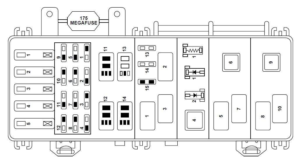
1999 Ford Ranger Fuse Box Diagram Under Hood
The 1999 Ford Ranger is a reliable workhorse, but like any vehicle, electrical issues can arise. Understanding the fuse box diagram under the hood is crucial for diagnosing and resolving these problems yourself, saving you time and money. This article will provide a detailed breakdown of the 1999 Ford Ranger under-hood fuse box, its components, and how to use the diagram effectively. We'll cover everything from basic troubleshooting to safety precautions, making you a more confident DIY mechanic.
Purpose of the Under-Hood Fuse Box Diagram
The fuse box diagram is your roadmap to the electrical system. Without it, you're essentially troubleshooting blind. Here's why it's invaluable:
- Troubleshooting Electrical Problems: When a component stops working – headlights, wipers, radio – a blown fuse is often the culprit. The diagram tells you which fuse controls that circuit.
- Identifying Circuit Locations: Need to tap into a specific circuit for adding an aftermarket accessory, like a new stereo or auxiliary lights? The diagram shows you exactly where that circuit originates.
- Preventing Further Damage: Incorrectly replacing a fuse with a higher amperage can cause serious damage to wiring and components. The diagram ensures you use the correct fuse rating.
- General Understanding: Even if you're not currently facing an issue, familiarizing yourself with the diagram gives you a better understanding of your vehicle's electrical system, making you a more informed owner.
Key Specs and Main Parts
The under-hood fuse box in the 1999 Ford Ranger is typically located on the driver's side of the engine compartment, near the firewall. It's housed in a black plastic enclosure. Key components include:
- Fuses: These are sacrificial devices designed to protect circuits from overcurrent. When the current exceeds the fuse's rating, the fuse element melts, breaking the circuit. Fuses are rated in amperes (amps or A), which indicates the amount of current they can handle. Common ratings include 5A, 10A, 15A, 20A, 25A, and 30A.
- Relays: Relays are electromechanical switches that control high-current circuits using a low-current signal. They're used to switch things like headlights, fuel pumps, and air conditioning compressors. A relay consists of a coil, which, when energized, creates a magnetic field that pulls a switch closed, completing the high-current circuit.
- Fuse Box Housing: The plastic enclosure that protects the fuses and relays from the elements. It usually has a lid with a diagram printed on the inside.
- Connectors: These are the points where wiring harnesses connect to the fuse box, providing power and control signals.
Knowing the approximate location of these components is important for visual inspection, even before consulting the diagram. Check for any signs of damage, such as melted plastic or corrosion.
Symbols and Notation on the Fuse Box Diagram
Understanding the symbols and notation on the fuse box diagram is paramount. While the exact layout and symbology can vary slightly, here are some common elements:
- Fuse Numbers: Each fuse is assigned a number, usually printed on the diagram and often embossed next to the fuse itself in the fuse box. This number is the key to identifying the circuit it protects.
- Circuit Descriptions: Next to the fuse number, the diagram will list a brief description of the circuit the fuse protects, such as "Headlights," "Fuel Pump," "Radio," etc.
- Amperage Ratings: The diagram will indicate the correct amperage rating for each fuse (e.g., 15A). Using the wrong amperage fuse can lead to component damage or even a fire.
- Relay Symbols: Relays are typically represented by a schematic symbol showing a coil and a switch. The diagram may also indicate the relay's function (e.g., "Headlight Relay," "Fuel Pump Relay").
- Line Types: Different line types might indicate different wire gauges or circuit types. However, this is less common on a fuse box diagram compared to a full wiring schematic.
- Color Coding: While the fuse box diagram itself usually isn't color-coded, knowing the wire colors associated with specific circuits can be helpful when troubleshooting. You can usually find this information in the vehicle's wiring diagram (a separate document).
The diagram is usually printed on the inside of the fuse box cover. If it's missing or illegible, you can often find a replacement online or in your owner's manual.
How It Works: Protecting the Electrical System
The fuse box is the central protection point for your Ranger's electrical system. Each fuse is a weak link in a specific circuit. If there's an overcurrent situation (e.g., a short circuit), the fuse blows, interrupting the flow of electricity and preventing damage to the components on that circuit. This is why it's critical to replace a blown fuse with one of the same amperage. A higher amperage fuse won't protect the circuit adequately and could allow excessive current to flow, potentially causing a fire. A lower amperage fuse will simply blow prematurely.
Relays, on the other hand, act as remotely controlled switches. They allow a low-current signal from a switch or sensor to control a high-current circuit that powers a device. For example, the headlight switch sends a low-current signal to the headlight relay, which then closes the circuit to power the headlights.
Real-World Use: Basic Troubleshooting Tips
Here's how to use the fuse box diagram to troubleshoot common electrical problems:
- Identify the Symptom: What component isn't working? Headlights? Radio? Wipers?
- Consult the Diagram: Locate the fuse or relay associated with the non-functioning component.
- Inspect the Fuse: Visually inspect the fuse. If the filament inside is broken, the fuse is blown. You can also use a multimeter to check for continuity across the fuse. A blown fuse will have no continuity.
- Replace the Fuse: Replace the blown fuse with a new fuse of the same amperage.
- Test the Circuit: Turn on the component that wasn't working to see if the new fuse fixes the problem.
- If the Fuse Blows Again: If the new fuse immediately blows, there's a short circuit or overload in the circuit. This requires further investigation by an experienced mechanic or careful tracing of the wiring.
- Relay Testing: Relays can be tested by swapping them with a known good relay of the same type. If swapping the relay fixes the problem, the original relay is faulty. You can also use a multimeter to test the relay's coil and switch contacts.
Before replacing any fuses, it's always a good idea to disconnect the negative battery terminal to prevent accidental shorts.
Safety Precautions
Working with electrical systems can be dangerous. Take these precautions:
- Disconnect the Battery: Always disconnect the negative battery terminal before working on the electrical system.
- Avoid Water: Never work on the electrical system in wet conditions.
- Use Insulated Tools: Use tools with insulated handles to prevent shocks.
- Identify High-Voltage Components: Be aware of high-voltage components like the ignition system and the alternator. Avoid touching these components while the engine is running.
- Never Bypass a Fuse: Never bypass a fuse by using a wire or other conductive material. This can cause serious damage or a fire.
- Airbag circuits: Be extremely careful when working near airbag circuits. Improper handling could cause accidental deployment. It is advisable to consult a professional for airbag-related issues.
High-amperage fuses and relays controlling critical systems (e.g., fuel pump, ignition) should be handled with extra care. A failure in these circuits can have significant consequences.
Remember, if you're not comfortable working on the electrical system, it's always best to consult a qualified mechanic.
We have a downloadable copy of the 1999 Ford Ranger Under-Hood Fuse Box Diagram available for you. This resource will be invaluable for your DIY projects and troubleshooting needs. Contact us through our website to receive the file.