1999 Honda Accord Distributor Wiring Diagram
The 1999 Honda Accord, a workhorse on the roads, relies on a well-functioning distributor for optimal engine performance. Understanding its wiring diagram isn't just for seasoned mechanics; it empowers any intermediate car owner or DIY enthusiast to diagnose, repair, and even upgrade their ignition system. This article breaks down the complexities of the 1999 Accord's distributor wiring, making it accessible and practical for your automotive endeavors.
Purpose of Understanding the Distributor Wiring Diagram
Why bother with the diagram? Simply put, it's your roadmap for anything involving the distributor. Here’s why it's invaluable:
- Troubleshooting Ignition Problems: Is your car sputtering, misfiring, or refusing to start? The wiring diagram helps you pinpoint shorts, open circuits, or faulty connections within the distributor circuit.
- Performing Repairs: Whether replacing a sensor, fixing a broken wire, or swapping out the entire distributor, the diagram ensures you connect everything correctly.
- Understanding System Operation: Gaining insights into how the distributor interacts with the ignition control module (ICM) and the engine control unit (ECU) fosters a deeper understanding of your car's inner workings.
- Performing Upgrades and Modifications: Thinking about aftermarket ignition components? The diagram helps you integrate them safely and effectively.
Key Specs and Main Parts of the 1999 Accord Distributor
Before diving into the diagram itself, let's familiarize ourselves with the key components and specifications relevant to the 1999 Honda Accord distributor:
- Distributor Type: Internal Coil Distributor (ICD). This means the ignition coil is housed within the distributor body.
- Engine Compatibility: This diagram primarily applies to the F23A1 (2.3L 4-cylinder) engine. While similar principles apply to other engine variants, be sure to consult the correct diagram for your specific engine code.
- Distributor Components:
- Ignition Coil: Generates the high voltage needed to ignite the air-fuel mixture.
- Ignition Control Module (ICM) / Igniter: Controls the timing and duration of the spark based on signals from the ECU.
- Camshaft Position Sensor (CMP): Detects the position of the camshaft, providing crucial timing information to the ECU.
- Crankshaft Position Sensor (CKP): This sensor is typically mounted outside the distributor; however, understanding how it interrelates is key to troubleshooting no start conditions.
- Distributor Cap: A protective cover that houses the rotor and distributes the high-voltage spark to the correct spark plugs.
- Rotor: A rotating arm inside the distributor cap that directs the high-voltage spark to the appropriate spark plug terminal.
- Pick-up Coil: Generates a pulse that tells the ICM when to fire the ignition coil.
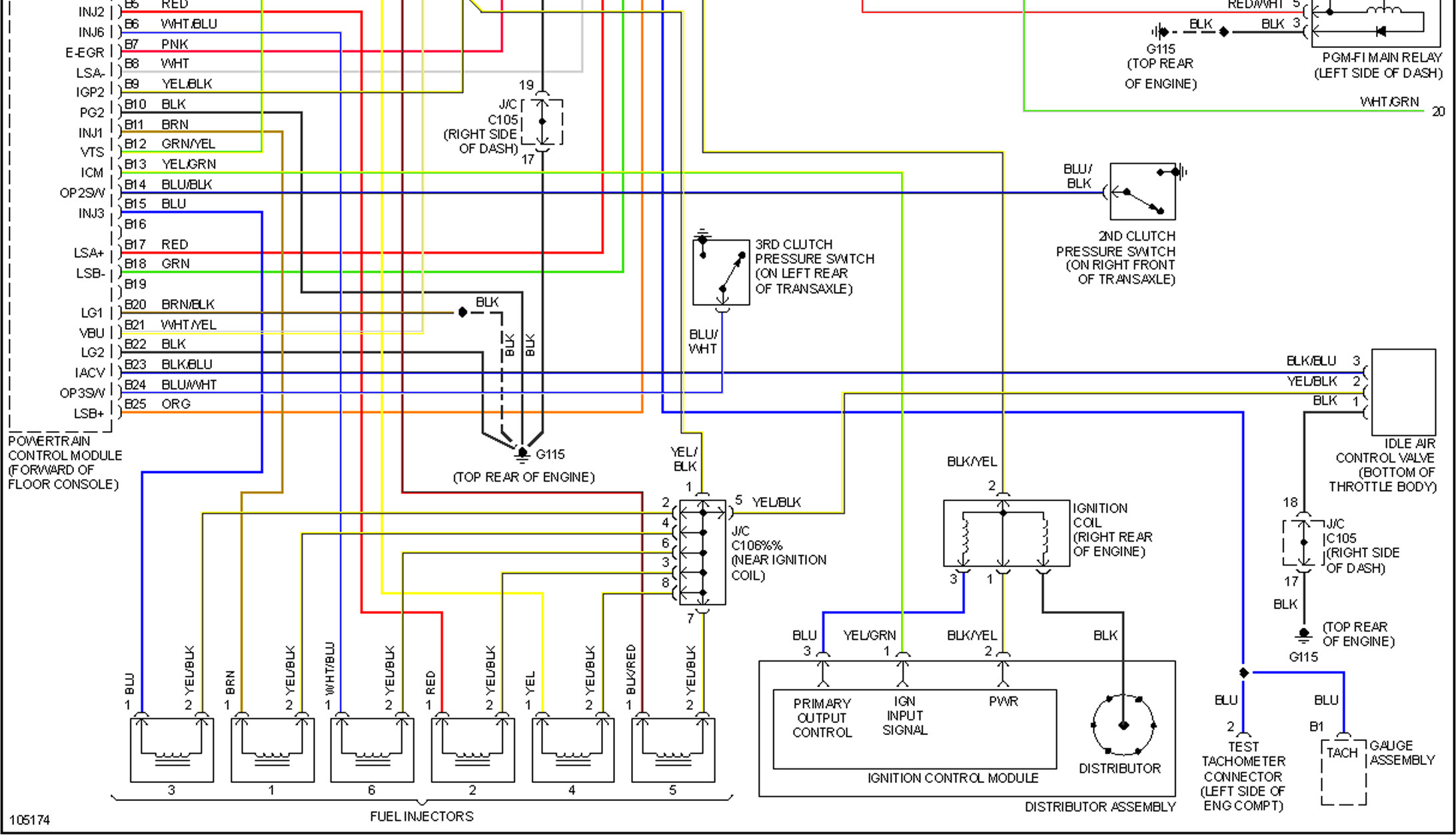
Decoding the Symbols in the Wiring Diagram
Wiring diagrams use standardized symbols to represent electrical components and connections. Here's a breakdown of common symbols you'll encounter:
- Solid Lines: Represent wires. Thicker lines may indicate wires carrying more current.
- Dashed Lines: Often represent shielding or grounds.
- Circles: Can represent terminals, connectors, or splices. Filled circles often indicate ground connections.
- Rectangles: Usually represent components like the ICM or sensors.
- Coil Symbol (squiggly line): Represents the ignition coil.
- Ground Symbol: Indicates a connection to the vehicle's chassis, providing a return path for the electrical current.
- Color Codes: Wires are often color-coded for identification. Common colors include:
- BLK (Black): Ground
- WHT (White): Often power or signal
- BLU (Blue): Signal
- GRN (Green): Signal or sensor input
- YEL (Yellow): Signal
- RED (Red): Power
It's crucial to have the correct diagram for your specific model year and trim level, as wiring configurations can vary.
How the 1999 Accord Distributor Works
The distributor's primary function is to accurately distribute high-voltage spark to the spark plugs in the correct firing order. Here's a simplified overview of the process:
- The CKP sensor sends a signal to the ECU indicating crankshaft position and engine speed.
- The CMP sensor, located inside the distributor, provides the ECU with information about camshaft position.
- Based on these inputs, the ECU determines the optimal ignition timing and sends a signal to the ICM.
- The ICM controls the ignition coil, causing it to generate a high-voltage pulse.
- The high-voltage pulse is sent to the distributor cap.
- The rotor, spinning inside the distributor cap, directs the high-voltage spark to the appropriate spark plug terminal, firing the corresponding cylinder.
This precisely timed spark ignites the air-fuel mixture in the cylinder, initiating the combustion process and driving the piston.
Real-World Use: Basic Troubleshooting Tips
Using the wiring diagram, you can perform basic troubleshooting. Here are a few scenarios:
- No Spark: Use a multimeter to check for voltage at the ignition coil's primary terminals. If there's no voltage, trace the wiring back to the ICM and the power source.
- Misfire: If only one cylinder is misfiring, check the spark plug wire, spark plug, and distributor cap terminal for that cylinder. If multiple cylinders are misfiring, suspect a problem with the ignition coil, ICM, or ECU.
- Erratic Timing: Check the wiring and connections to the CMP sensor. A faulty CMP sensor can cause incorrect ignition timing, leading to poor performance and fuel economy.
- P0300 (Random Misfire): This is a tricky code that often indicates a problem with the entire system. Use the diagram to check the integrity of all wiring, sensors, and components related to the ignition system.
Important! Always disconnect the negative battery cable before working on the electrical system to prevent accidental shorts.
Safety Considerations
Working with the ignition system involves high voltage and potentially dangerous components. Observe these safety precautions:
- High Voltage: The ignition coil generates extremely high voltage (tens of thousands of volts). Never touch the spark plug wires or the ignition coil while the engine is running or the ignition is turned on.
- Fuel Leaks: Be aware of potential fuel leaks when working around the distributor. Fuel is highly flammable.
- Proper Grounding: Ensure proper grounding when testing electrical circuits. A faulty ground can lead to inaccurate readings and potential damage to components.
- Disconnect Battery: As mentioned previously, disconnect the negative battery cable before starting any electrical work.
- Use Proper Tools: Use insulated tools designed for automotive electrical work.
Remember, if you're not comfortable working with electrical systems, consult a qualified mechanic.
Armed with this understanding of the 1999 Honda Accord distributor wiring diagram, you can confidently tackle ignition system repairs, upgrades, and troubleshooting. Remember to always double-check your work and prioritize safety. We have the full downloadable wiring diagram to help you further.