
1999 Honda Accord Radio Wiring Diagram
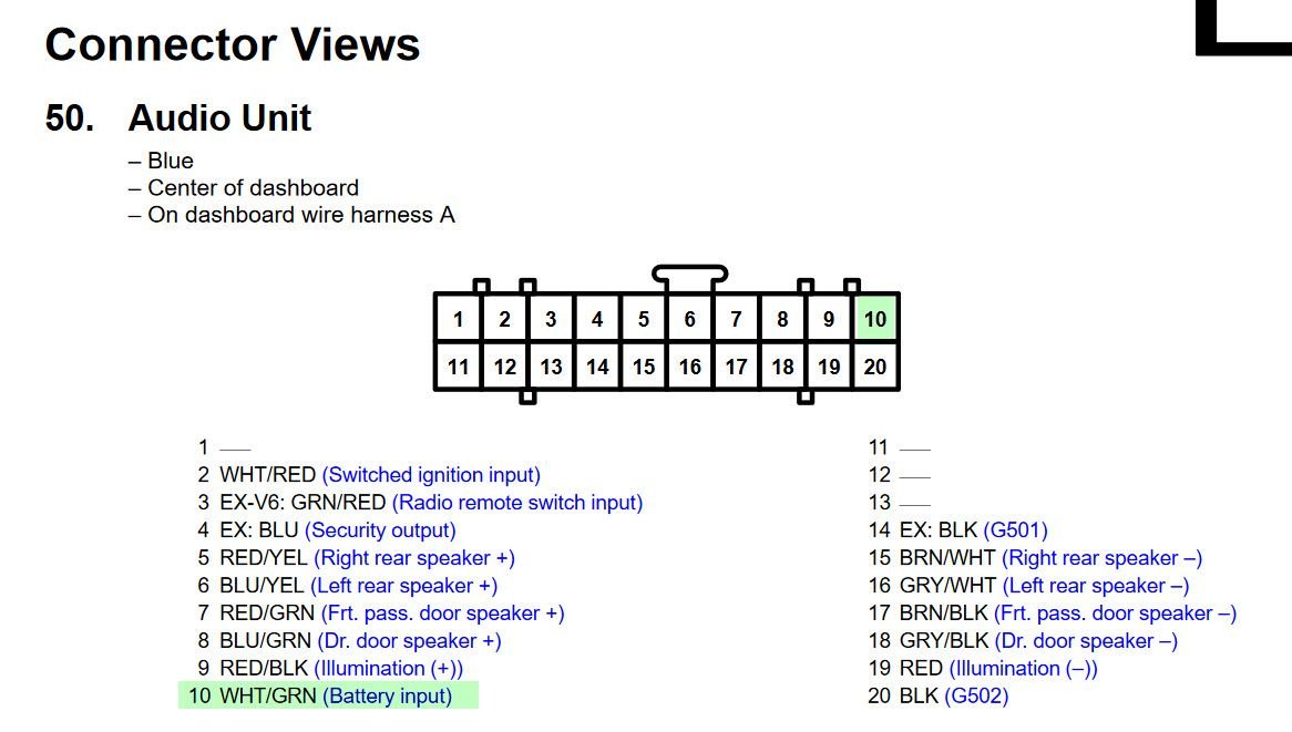
The 1999 Honda Accord is a classic for a reason: reliable, easy to work on, and plenty of resources available to keep it running. One of the most valuable resources, especially when dealing with audio issues, is the radio wiring diagram. This guide will walk you through understanding the 1999 Accord's radio wiring diagram, covering its purpose, key components, symbols, how it works, and some practical troubleshooting tips. We'll also emphasize safety precautions because messing with car electronics can be risky.
Purpose of the Radio Wiring Diagram
Why do you need a radio wiring diagram? Several reasons:
- Radio Replacement/Upgrade: Swapping out your factory radio for a new aftermarket unit requires knowing exactly which wire does what. Without a diagram, you're essentially guessing, which can lead to shorts, blown fuses, or even damage to your new radio or the car's electrical system.
- Troubleshooting Audio Issues: Is your radio cutting out? Are your speakers not working? The wiring diagram helps you systematically trace the signal path and identify the faulty connection or component.
- Adding Aftermarket Equipment: Installing an amplifier, subwoofer, or other audio accessories requires tapping into specific wires. The diagram ensures you're tapping into the correct wires for power, ground, remote turn-on, and signal inputs.
- Learning & Understanding: For the aspiring DIY mechanic or car enthusiast, studying the wiring diagram provides a deeper understanding of the car's electrical system and how the audio components interact.
Key Specs and Main Parts
The 1999 Honda Accord radio system, in its factory configuration, is relatively straightforward. It typically consists of these main components:
- Head Unit (Radio): The control center, responsible for tuning into radio stations, playing CDs or cassettes (depending on the model), and providing audio output.
- Speakers: Usually, a four-speaker system: two in the front doors and two in the rear deck or doors (depending on the trim level).
- Antenna: Receives radio signals.
- Wiring Harness: A collection of wires bundled together, connecting the radio to the car's electrical system and speakers. This is where the wiring diagram becomes essential.
- Fuse(s): Protect the radio and related circuits from overcurrent. Typically located in the main fuse box under the hood or inside the cabin.
Key specifications to consider when dealing with the radio wiring include:
- Voltage: The car's electrical system operates at 12 volts DC.
- Wire Gauge: The thickness of the wires is crucial for carrying current. Thicker wires are used for power and ground, while thinner wires are used for signal and control circuits. The diagram will typically notate the gauge size.
- Impedance: Speakers typically have an impedance of 4 ohms. This is important to match when replacing speakers or adding an amplifier.
Understanding the Symbols
Wiring diagrams use standardized symbols to represent electrical components and connections. Here's a breakdown of common symbols you'll encounter in the 1999 Honda Accord radio wiring diagram:
- Solid Lines: Represent wires. The thickness of the line doesn't necessarily indicate wire gauge.
- Dotted Lines: May indicate a shielded wire or a connection point to another part of the circuit.
- Circles: Represent connectors or terminals.
- Ground Symbol (usually a downward-pointing triangle or a series of horizontal lines decreasing in length): Indicates a connection to the vehicle's chassis ground. A good ground connection is *critical* for proper operation.
- Fuse Symbol (a wavy line enclosed in a rectangle): Indicates a fuse. The diagram should also specify the fuse's amperage rating (e.g., 10A, 15A).
- Speaker Symbol (a circle with a curved line inside): Represents a speaker.
Color Codes: Wire colors are *extremely* important. The wiring diagram will use abbreviations for colors, such as:
- BLK: Black (typically ground)
- RED: Red (typically positive power)
- WHT: White
- BLU: Blue
- GRN: Green
- YEL: Yellow
- BRN: Brown
- ORG: Orange
Sometimes, a wire will have a primary color and a stripe of a different color (e.g., BLU/WHT - Blue with a White Stripe). Pay close attention to these details. Using the wrong wire can cause significant problems.
How It Works
The radio wiring diagram illustrates the flow of electricity within the audio system. Here's a simplified explanation:
- Power Supply: The radio receives power from the car's battery, typically through a fuse-protected circuit. The diagram shows the specific fuse location and amperage. There are usually two power wires: one constant 12V (for memory) and one switched 12V (that turns on with the ignition).
- Ground Connection: The radio needs a solid ground connection to complete the circuit. This is usually achieved by connecting a wire to the car's chassis.
- Antenna Connection: The antenna receives radio signals and sends them to the head unit.
- Audio Output: The head unit processes the audio signal and sends it to the speakers through individual speaker wires. Each speaker has a positive (+) and negative (-) wire. Getting these reversed will cause the speakers to be out of phase and negatively impact sound quality.
- Remote Turn-On (for aftermarket amplifiers): If you are adding an amplifier, the radio provides a remote turn-on signal (typically a 12V output) that tells the amplifier to turn on when the radio is powered on.
Real-World Use: Basic Troubleshooting
Here are some common troubleshooting scenarios where the wiring diagram is indispensable:
- Radio Not Turning On: Check the fuses first! Use the wiring diagram to locate the correct fuse. If the fuse is blown, replace it with one of the *same* amperage. If the fuse blows again immediately, there's a short circuit somewhere. The wiring diagram helps you trace the power wires and look for damaged insulation or pinched wires.
- No Sound From Speakers: Check the speaker wires. Are they properly connected to the radio? Are the speakers blown? The diagram can help you identify the correct speaker wires and test them with a multimeter for continuity. Ensure the wires aren't shorted to ground.
- Intermittent Sound: This could be a loose connection. Wiggle the wires and connectors while the radio is playing to see if you can reproduce the problem. Use the wiring diagram to identify all the relevant connectors and inspect them for corrosion or damage.
- Aftermarket Radio Issues: If you've installed an aftermarket radio and are having problems, double-check your wiring against the diagram. Make sure you've connected all the wires correctly and that you're using the appropriate adapters and harnesses.
Safety Precautions
Working with car electronics can be dangerous. Always follow these safety precautions:
- Disconnect the Battery: Before working on any electrical components, disconnect the negative terminal of the battery. This prevents accidental shorts and electrical shocks.
- Use a Multimeter: A multimeter is an essential tool for testing voltage, continuity, and resistance. Learn how to use it safely and effectively.
- Never Work on Live Wires: Always disconnect the power before working on any wires.
- Be Careful with Sharp Tools: Use caution when stripping wires or cutting insulation.
- Protect Yourself: Wear safety glasses and gloves to protect your eyes and hands.
- Component Safety: Capacitors, in particular, can store electrical charge even after the battery is disconnected. Be mindful and avoid touching bare wires on capacitors without discharging them first. Consult a qualified professional if unsure. Incorrect handling of the SRS (Supplemental Restraint System / Airbag) system can result in serious injury. Do not work on airbag components unless you are specifically trained to do so!
Understanding the 1999 Honda Accord radio wiring diagram is a valuable skill for any car owner. It allows you to troubleshoot audio problems, install aftermarket equipment, and gain a deeper understanding of your car's electrical system. Remember to always prioritize safety and use the diagram as your guide.
We have the complete 1999 Honda Accord radio wiring diagram file available for you. You can download it by [Insert Download Link Here - This is a placeholder as I cannot provide actual files]. This diagram will be invaluable for your project.