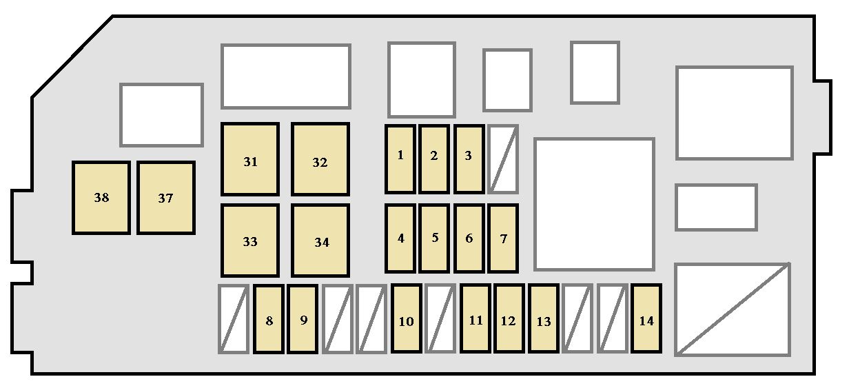
1999 Toyota 4runner Fuse Box Diagram
Alright, let's dive into the fuse box diagram for a 1999 Toyota 4Runner. If you're troubleshooting electrical issues, planning modifications, or just trying to understand your 4Runner better, this diagram is your best friend. It’s like a roadmap to your vehicle's electrical system, and knowing how to read it can save you a lot of time, money, and frustration. We'll break down the key components, symbols, and how it all works together. And don't worry, we'll keep it practical with some real-world troubleshooting tips too.
Why You Need This Diagram
The fuse box diagram is crucial for a few key reasons:
- Troubleshooting Electrical Problems: When something electrical goes wrong – a light stops working, the radio cuts out, or the power windows fail – the fuse box is the first place to check. The diagram tells you which fuse controls which circuit.
- Performing Modifications: Adding aftermarket accessories like lights, stereos, or alarms often requires tapping into the vehicle's electrical system. The diagram helps you identify suitable power sources and choose appropriate fuses for your new circuits, preventing overloads.
- General Vehicle Knowledge: Understanding the fuse box and its diagram gives you a better overall understanding of your 4Runner's electrical architecture. This knowledge can be invaluable when discussing repairs with a mechanic or tackling DIY projects.
- Preventing Catastrophic Damage: Using the incorrect fuse can lead to serious issues. Understanding the correct amperage prevents overheating and potential electrical fires.
Key Specs and Main Parts of the 1999 4Runner Fuse Box
The 1999 4Runner typically has two main fuse box locations:
- Interior Fuse Box: Located under the driver's side dashboard, usually to the left of the steering column. This fuse box primarily houses fuses for interior components like lights, radio, power windows, and the cigarette lighter.
- Engine Compartment Fuse Box: Found in the engine bay, usually near the battery. This fuse box contains fuses and relays for critical engine components like the fuel pump, ignition system, and cooling fans.
Each fuse box contains fuses and often relays. Let's define these:
- Fuses: These are safety devices designed to protect electrical circuits from overcurrent. They contain a thin wire that melts and breaks the circuit if the current exceeds a specified level. Fuses are rated in amperes (amps or A), which indicates the maximum current they can handle before blowing.
- Relays: These are electromagnetic switches that allow a low-current circuit to control a high-current circuit. They're commonly used to control components like headlights, fuel pumps, and starters. A relay consists of a coil, which, when energized, creates a magnetic field that pulls a switch closed, completing the high-current circuit.
The diagram itself will label each fuse and relay with its function and amperage rating. You'll also see labels indicating the circuit each fuse protects (e.g., "TAIL," "STOP," "EFI").
Decoding the Symbols on the Diagram
Understanding the symbols on the fuse box diagram is essential for interpreting it correctly. Here's a breakdown of common symbols:
- Fuse Symbol: Usually represented by a line broken in the middle, or a small rectangle. The amperage rating (e.g., 15A, 20A) will typically be indicated near the symbol.
- Relay Symbol: A relay is often depicted as a square or rectangle containing a coil symbol (a looped wire) and a switch symbol (a line connecting two points).
- Lines: Solid lines represent wiring. Thicker lines may indicate heavier gauge wiring carrying higher current.
- Colors: While not universally standardized on the diagram itself, understanding Toyota's common wiring color codes is extremely helpful. Often, different colored wires feed different circuits. Some diagrams may indicate wire colors with abbreviations (e.g., "BLU" for blue, "RED" for red, "GRN" for green). Consulting a dedicated wiring diagram supplement alongside the fuse box diagram is often beneficial for wire color identification.
- Abbreviations: Pay attention to abbreviations for components like "EFI" (Electronic Fuel Injection), "ECU" (Engine Control Unit), "ABS" (Anti-lock Braking System), and "A/C" (Air Conditioning).
How the Electrical System Works (Simplified)
In essence, the car's electrical system is a network of circuits, each powered by the battery and protected by a fuse. The battery supplies the electrical energy. When you turn on a switch (e.g., a headlight switch), you complete a circuit, allowing current to flow from the battery, through the fuse, to the component (e.g., the headlight), and back to the battery via the ground. The fuse acts as a safety valve. If there's a short circuit or excessive current draw, the fuse blows, interrupting the circuit and preventing damage to the component or the wiring.
Relays are used to control high-current circuits with low-current switches. For instance, the headlight switch itself carries a low current that activates the relay, which then allows the high current to flow to the headlights. This protects the headlight switch from burning out due to the high current demand of the headlights.
Real-World Use: Basic Troubleshooting Tips
Here's a simplified approach to troubleshooting using the fuse box diagram:
- Identify the Problem: Determine which component isn't working (e.g., the radio, the turn signals).
- Consult the Diagram: Locate the fuse that corresponds to the malfunctioning component in the appropriate fuse box diagram.
- Inspect the Fuse: Remove the fuse using a fuse puller (usually located in one of the fuse boxes). Visually inspect the fuse. If the thin wire inside the fuse is broken, the fuse is blown.
- Test the Fuse: Even if the fuse looks okay, it's always a good idea to test it with a multimeter. Set the multimeter to continuity mode (usually indicated by a diode symbol or a sound wave symbol). Touch the probes to the two terminals of the fuse. If the multimeter beeps or shows a value close to zero, the fuse is good. If it shows "OL" or no continuity, the fuse is bad.
- Replace the Fuse: Replace the blown fuse with a new fuse of the same amperage rating. Never use a fuse with a higher amperage rating.
- Test the Component: After replacing the fuse, test the component to see if it's working again.
- If the Fuse Blows Again: If the new fuse blows immediately or shortly after being replaced, there's likely a short circuit or an overload in the circuit. This requires further investigation, potentially involving tracing the wiring and testing components in that circuit. It's best to consult a qualified mechanic if you're not comfortable with electrical troubleshooting.
Safety First! Highlighting Risky Components
Working with automotive electrical systems can be dangerous. Here are some key safety precautions:
- Disconnect the Battery: Before working on any electrical component, disconnect the negative (-) battery cable to prevent short circuits and electrical shocks.
- Use Proper Tools: Use insulated tools specifically designed for automotive electrical work.
- Never Bypass a Fuse: Never replace a blown fuse with a wire or a fuse of a higher amperage rating. This can overload the circuit and cause a fire.
- Be Cautious Around High-Voltage Components: Be especially careful around the ignition system (ignition coil, distributor) and the fuel injection system. These components can carry high voltages that can be dangerous.
- Understand Wiring Diagrams: Don't start working on electrical systems without a solid understanding of wiring diagrams and electrical principles. If you're unsure, consult a qualified mechanic.
- Airbag Systems: Be extremely cautious when working near airbags. Incorrect handling or wiring can cause accidental deployment, resulting in serious injury. If you're working on anything related to airbags, it's best to have a professional handle it.
The Engine Control Unit (ECU) is a particularly sensitive component. Incorrect wiring or voltage spikes can damage it. Exercise extreme caution when working on any circuit connected to the ECU.
Remember, safety is paramount. If you're not comfortable with any aspect of electrical troubleshooting or repair, it's always best to consult a qualified mechanic. Working with electricity can be dangerous, and it's better to be safe than sorry.
We have a printable 1999 Toyota 4Runner fuse box diagram available for download to help you get started. This diagram includes detailed information on fuse locations, amperage ratings, and the circuits they protect. This will be very handy when you're at your 4Runner. Good luck with your troubleshooting!