
2 Pole Starter Solenoid Wiring Diagram
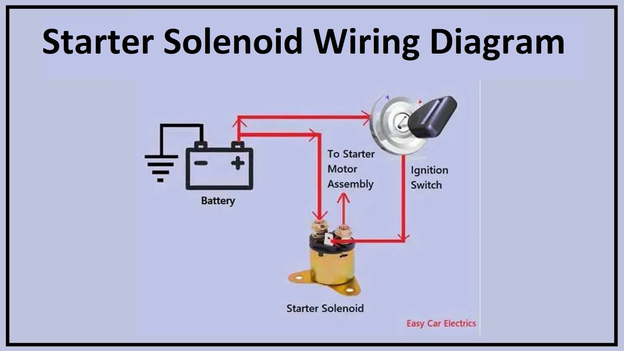
Understanding the 2-pole starter solenoid wiring diagram is crucial for anyone delving into automotive electrical systems. Whether you're tackling a no-start issue, upgrading your electrical system, or simply expanding your automotive knowledge, this guide will provide a clear and comprehensive overview. We'll break down the diagram, explain its components, and equip you with the knowledge to confidently troubleshoot and maintain your vehicle's starting system. And because having a visual aid is paramount, we have a downloadable diagram available at the end of this article for your reference.
Purpose of a 2-Pole Starter Solenoid Wiring Diagram
A starter solenoid wiring diagram serves several important purposes:
- Diagnosis and Repair: The primary function is to provide a visual roadmap for diagnosing and repairing starting system problems. By following the wiring diagram, you can trace circuits, identify faulty components, and ensure correct wiring connections during repairs.
- Upgrades and Modifications: When upgrading your electrical system (e.g., installing a high-torque starter), the diagram helps you understand the existing wiring and make necessary modifications safely and correctly.
- Educational Tool: The diagram is an invaluable learning resource for understanding the fundamental principles of automotive electrical circuits and how different components interact.
- Preventing Electrical Fires: Incorrect wiring can lead to short circuits and potentially dangerous electrical fires. Using a diagram ensures proper connections and minimizes this risk.
Key Specifications and Main Parts
Before diving into the diagram itself, let's define the key specifications and parts of a typical 2-pole starter solenoid system:
- Battery: The power source for the entire system (typically 12V in automotive applications).
- Ignition Switch: The switch that initiates the starting sequence when you turn the key.
- Starter Solenoid: An electromagnetically operated switch that provides a high-current connection to the starter motor. A 2-pole solenoid, for our purposes, means it has two large terminals for the battery and starter connections, and a smaller terminal for the signal wire from the ignition switch.
- Starter Motor: The electric motor that turns the engine's flywheel to initiate combustion.
- Wiring Harness: The collection of wires that connect all the components. Wire gauge (thickness) is a critical specification. The heavier gauge wires (e.g., 4 AWG, 6 AWG) carry high current to the starter motor.
- Ground Connection: A critical connection to the vehicle's chassis, providing a return path for the electrical current. A good, clean ground is essential.
Key Specifications to Note:
- Voltage Rating: Typically 12V in automotive applications. Ensure all components are rated for this voltage.
- Current Rating: The solenoid and wiring must be capable of handling the high current draw of the starter motor (often hundreds of amps).
- Wire Gauge: Use appropriate wire gauge based on current requirements. Undersized wiring can cause voltage drop and overheating.
Understanding the Symbols in the Wiring Diagram
Wiring diagrams use standardized symbols to represent components and connections. Understanding these symbols is essential for interpreting the diagram correctly.
- Lines: Represent wires connecting the components. Thicker lines often indicate heavier gauge wires.
- Colors: Wires are often color-coded (e.g., red for positive, black for ground). Note the color code legend on the diagram. Color-coding aids in tracing circuits.
- Battery Symbol: Depicted as a series of short and long parallel lines.
- Switch Symbol: Represents the ignition switch. It shows the switch in its 'off' or 'open' position.
- Solenoid Symbol: Often shown as a coil with a switch symbol. The coil represents the electromagnet.
- Starter Motor Symbol: Usually represented as a circle with an "M" inside.
- Ground Symbol: Depicts the connection to the vehicle's chassis.
Color coding is extremely important. Common color codes include:
- Red: Typically indicates a positive (+) connection, often from the battery.
- Black: Usually represents ground (-) or a return path.
- Other Colors: Other colors (e.g., blue, yellow, green) are used for various circuits and control signals. Refer to the specific diagram's legend for the color assignments.
How It Works: The Starting Sequence
The 2-pole starter solenoid system works as follows:
- Ignition Switch Activation: When you turn the ignition key to the "start" position, the ignition switch sends a small current (the control signal) to the starter solenoid.
- Solenoid Activation: This small current energizes the solenoid's electromagnet.
- Contact Closure: The energized electromagnet pulls a plunger, mechanically closing a heavy-duty switch (contacts) within the solenoid.
- High-Current Flow: Closing the contacts completes the circuit between the battery and the starter motor. A large amount of current then flows from the battery, through the solenoid's contacts, and to the starter motor.
- Starter Motor Operation: The starter motor spins, engaging with the flywheel and turning the engine.
- Release: When you release the ignition key, the current to the solenoid is cut off, the electromagnet de-energizes, the contacts open, and the starter motor stops.
The solenoid acts as a relay, using a small current from the ignition switch to control a much larger current needed to operate the starter motor. This protects the ignition switch from damage due to high current flow.
Real-World Use: Basic Troubleshooting
Here are some basic troubleshooting tips when dealing with a no-start condition, using the wiring diagram as a guide:
- Check Battery Voltage: Use a multimeter to ensure the battery has adequate voltage (around 12.6V when fully charged). A dead battery is the most common cause of no-start issues.
- Inspect Connections: Check all wiring connections for corrosion, looseness, or damage. Pay particular attention to the battery terminals, solenoid terminals, and ground connections. Clean and tighten as needed.
- Test Solenoid Activation: Have someone turn the ignition key to the "start" position while you listen for a "click" from the solenoid. If you hear the click, the solenoid is likely receiving power from the ignition switch. If not, there may be a problem with the ignition switch, wiring, or the solenoid itself.
- Voltage Drop Test: Use a multimeter to measure the voltage drop across the solenoid when attempting to start the engine. Excessive voltage drop indicates a problem within the solenoid (e.g., corroded contacts).
- Check Ground Connection: Ensure a solid ground connection between the engine block and the vehicle's chassis. Use a wire brush to clean the contact surfaces.
If the solenoid clicks but the starter motor doesn't engage, the problem may be with the starter motor itself or the solenoid's contacts. If nothing happens at all, the problem is likely an open circuit in the wiring, a faulty solenoid, or a dead battery.
Safety Precautions
Working with automotive electrical systems involves inherent risks. Take the following safety precautions:
- Disconnect the Battery: Always disconnect the negative battery cable before working on any electrical component. This prevents accidental short circuits and electrical shocks.
- Use Proper Tools: Use insulated tools specifically designed for automotive electrical work.
- Wear Safety Glasses: Protect your eyes from sparks and debris.
- Be Aware of High Current: The starter motor circuit carries very high current. Avoid touching any bare wires or terminals while the system is active.
- Consult a Professional: If you are unsure about any aspect of the repair, consult a qualified mechanic.
Important note: The battery and starter circuits are capable of delivering a large amount of current very quickly. Short circuits in these areas can cause serious burns and electrical fires. Exercise extreme caution.
By understanding the 2-pole starter solenoid wiring diagram and following these guidelines, you'll be well-equipped to diagnose and resolve common starting system problems. Remember to always prioritize safety and consult a professional if needed.
To further assist you, we've created a detailed 2-Pole Starter Solenoid Wiring Diagram for you to download. Having a visual aid will make all the difference in your understanding and troubleshooting. You can download the diagram here.