2 Stroke And 4 Stroke Engine Diagram
Understanding the inner workings of your engine is crucial whether you're tackling basic maintenance, contemplating performance modifications, or simply want to impress your friends with your mechanical knowledge. Engine diagrams are the Rosetta Stone of automotive repair and modification. This article provides a detailed, yet approachable, explanation of both 2-stroke and 4-stroke engine diagrams, empowering you to interpret these schematics and apply them to real-world scenarios.
Purpose of Engine Diagrams
Why bother learning to read an engine diagram? Simply put, they're indispensable for:
- Diagnosis: Identifying faulty components and tracing the flow of fluids (fuel, oil, coolant) and electricity through the engine's systems.
- Repair: Guiding disassembly and reassembly procedures, ensuring proper component placement and torque specifications.
- Modification: Planning and executing performance upgrades, such as turbocharging, supercharging, or engine swaps. Understanding the existing layout helps in integrating new systems.
- Learning: Gaining a deeper understanding of engine operation and design principles. Seeing the relationships between parts visually solidifies the theory.
- Troubleshooting: Systematically isolating problems by following the diagram to see where the normal flow of operations is disrupted.
Key Specs and Main Parts: Common to Both Engine Types
While 2-stroke and 4-stroke engines differ significantly in their operating cycles, they share core components. Understanding these is fundamental to interpreting any engine diagram.
Common Components:
- Cylinder Block: The main structure of the engine, containing the cylinders.
- Cylinder Head: Sits atop the cylinder block, housing the valves (4-stroke only), spark plugs, and combustion chamber.
- Piston: A cylindrical component that moves up and down inside the cylinder, converting combustion pressure into mechanical force.
- Connecting Rod (Con-Rod): Connects the piston to the crankshaft.
- Crankshaft: Converts the linear motion of the pistons into rotational motion, which drives the transmission.
- Spark Plug: Ignites the air-fuel mixture in the cylinder. (Gasoline engines only)
- Intake and Exhaust Ports: Openings in the cylinder (2-stroke) or cylinder head (4-stroke) that allow air and fuel to enter, and exhaust gases to exit, the cylinder.
Beyond these core components, diagrams often include details about:
- Lubrication System: Showing the oil pump, oil filter, oil galleries, and oil jets.
- Cooling System: Depicting the water pump, radiator, thermostat, and coolant passages.
- Fuel System: Illustrating the fuel pump, fuel injectors (or carburetor), fuel lines, and fuel filter.
- Ignition System: Showing the ignition coil, distributor (if applicable), spark plugs, and wiring.
Symbols: Decoding the Diagram's Language
Engine diagrams use a standardized set of symbols to represent different components and systems. Learning these symbols is essential for effective interpretation.
Common Symbols:
- Lines: Represent pipes, hoses, wires, or mechanical linkages. Solid lines typically indicate fluid flow (oil, fuel, coolant), while dashed lines may represent vacuum lines or electrical circuits. The thickness of a line can sometimes denote the size of the passage or wire gauge.
- Arrows: Indicate the direction of flow (fluid or electricity).
- Circles: Often represent gauges, sensors, or filters.
- Rectangles: Can represent various components, such as pumps, relays, or control modules. The rectangle might contain a smaller symbol that is more specific.
- Triangles: Frequently used to depict valves or check valves.
- Colors: Color coding is used on some diagrams to differentiate between different fluids or electrical circuits. For example, red might indicate fuel lines, blue might indicate coolant lines, and black might indicate ground wires. Always refer to the diagram's legend for color definitions.
- Numerical Codes: Many diagrams use numerical codes to identify specific components. These codes are typically listed in a key or parts list accompanying the diagram.
It's crucial to remember that symbol usage can vary slightly between manufacturers and diagram types. Always consult the diagram's legend or key for clarification.
How It Works: 2-Stroke vs. 4-Stroke Cycles
The fundamental difference between 2-stroke and 4-stroke engines lies in the number of piston strokes required to complete a full combustion cycle. This significantly impacts the engine's design and operation.
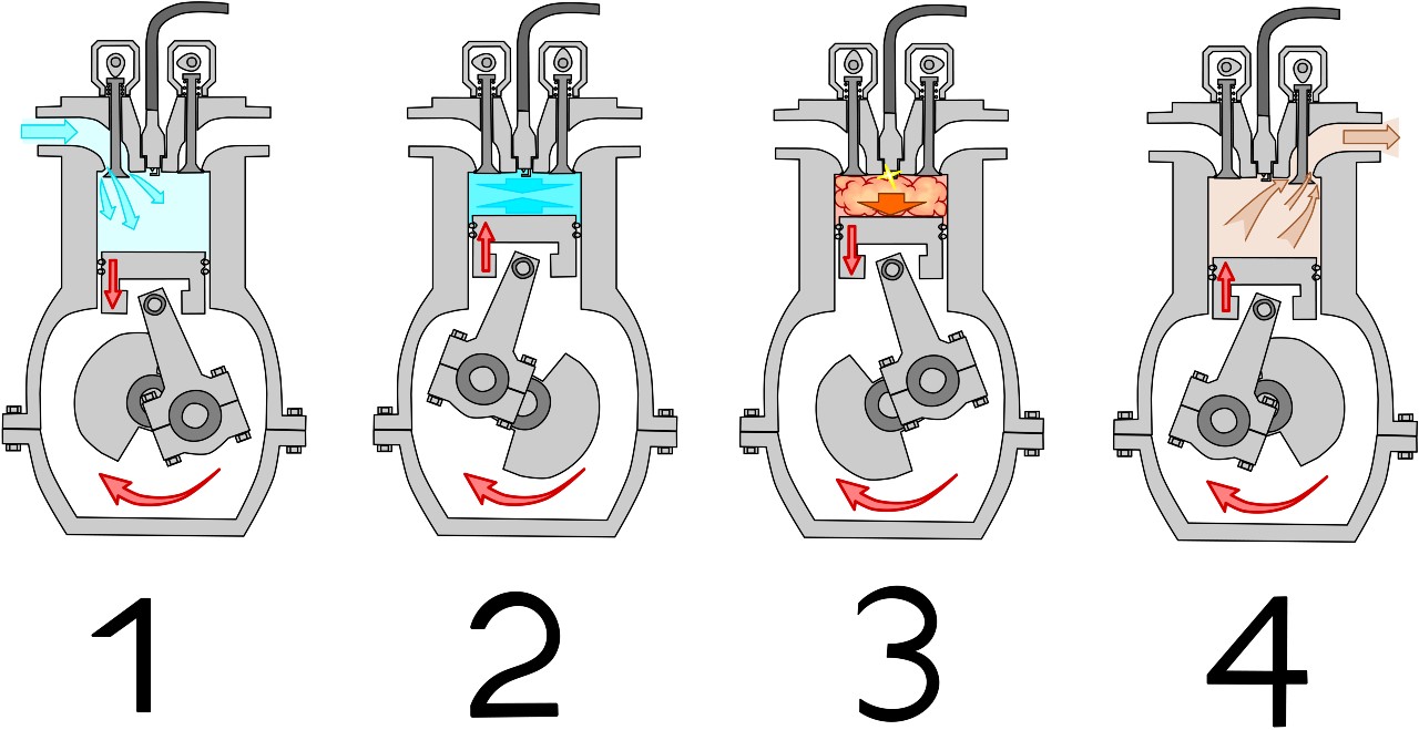
4-Stroke Engine Cycle:
The 4-stroke engine completes its cycle in four distinct strokes of the piston:
- Intake: The piston moves down, creating a vacuum that draws the air-fuel mixture into the cylinder through the intake valve.
- Compression: The piston moves up, compressing the air-fuel mixture. Both intake and exhaust valves are closed.
- Combustion (Power): The spark plug ignites the compressed air-fuel mixture, creating a rapid expansion of gases that forces the piston down.
- Exhaust: The piston moves up, pushing the exhaust gases out of the cylinder through the exhaust valve.
Note the importance of valves in the 4-stroke engine. Valves are mechanically operated to open and close the intake and exhaust ports at precise timings.
2-Stroke Engine Cycle:
The 2-stroke engine completes its cycle in only two strokes of the piston:
- Compression & Intake: As the piston moves up, it compresses the air-fuel mixture in the combustion chamber. Simultaneously, it creates a vacuum in the crankcase, drawing in a fresh charge of air-fuel mixture through the intake port.
- Combustion & Exhaust: The spark plug ignites the compressed air-fuel mixture, forcing the piston down. As the piston nears the bottom of its stroke, it uncovers the exhaust port, allowing exhaust gases to escape. Shortly after, it uncovers the transfer port, allowing the fresh air-fuel mixture from the crankcase to enter the cylinder, scavenging the remaining exhaust gases.
The 2-stroke engine relies on ports in the cylinder wall, opened and closed by the piston itself, to control the intake and exhaust processes, rather than valves.
Diagrams for each type of engine will clearly highlight the presence (or absence) of valves and the location of the intake, exhaust, and transfer ports.
Real-World Use: Basic Troubleshooting
Here's how you can use engine diagrams for basic troubleshooting:
- No Start: Trace the fuel system diagram to ensure fuel is reaching the injectors (or carburetor). Check the ignition system diagram to verify spark plug operation.
- Overheating: Consult the cooling system diagram to check for coolant leaks, a faulty thermostat, or a malfunctioning water pump.
- Oil Leaks: Use the lubrication system diagram to pinpoint the source of the leak, such as a worn seal or gasket.
- Performance Issues: Understanding the vacuum line routing diagram can help identify vacuum leaks, which can significantly impact engine performance.
Always consult the vehicle's service manual for specific diagnostic procedures and testing methods. The diagram is a map, but you need the manual to interpret the road signs!
Safety Considerations
Working on engines involves potential hazards. Be aware of the following:
- High Temperatures: Exhaust manifolds, cylinder heads, and coolant can reach extremely high temperatures. Allow the engine to cool completely before working on it.
- High Pressure: Fuel systems can be under high pressure. Relieve pressure before disconnecting fuel lines.
- Electrical Shock: The ignition system carries high voltage. Disconnect the battery before working on the ignition system.
- Moving Parts: Keep hands and clothing clear of moving parts, such as belts, pulleys, and the crankshaft.
- Flammable Materials: Fuel and oil are highly flammable. Work in a well-ventilated area and keep open flames away.
Always wear appropriate safety gear, including eye protection, gloves, and hearing protection.
Diagram Download
We have a comprehensive set of 2-stroke and 4-stroke engine diagrams available for download. This collection includes various engine configurations and levels of detail, offering a valuable resource for your automotive endeavors. These diagrams are in PDF format for easy viewing and printing.
Understanding engine diagrams is a rewarding skill that empowers you to tackle a wide range of automotive tasks with confidence. By mastering the symbols, understanding the operating cycles, and applying this knowledge to real-world scenarios, you'll gain a deeper appreciation for the engineering marvel that powers your vehicle.