
2 Ton Hydraulic Floor Jack Parts Diagram
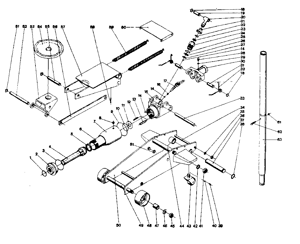
Understanding the anatomy of your 2-ton hydraulic floor jack is crucial whether you're planning to tackle repairs, perform preventative maintenance, or simply expand your automotive knowledge. This article provides a detailed breakdown of a typical 2-ton hydraulic floor jack parts diagram, explaining each component's function, its role in the lifting process, and common troubleshooting scenarios. Knowing the inner workings allows you to perform basic repairs, diagnose problems efficiently, and ultimately work more safely around your vehicle. And remember, we have a high-resolution diagram available for download to help you follow along.
Purpose of the Diagram
A parts diagram isn't just a pretty picture; it's a vital tool. It serves several key purposes:
- Repair Identification: Quickly identify the specific part you need to replace. Knowing the correct name avoids confusion when ordering replacements.
- Assembly Reference: If you've disassembled the jack for cleaning or repair, the diagram acts as a guide for reassembly, ensuring everything is put back in the correct order and orientation.
- Operational Understanding: Visualizing the components helps you understand the hydraulic circuit and how the jack generates lifting force.
- Troubleshooting Aid: By visually connecting a symptom (e.g., the jack won't lift) to a specific part (e.g., a leaking seal), you can narrow down potential causes.
Key Specs and Main Parts
Before diving into the diagram, let's cover some essential specifications and the main components found in most 2-ton hydraulic floor jacks. A "2-ton" jack has a rated lifting capacity of 4,000 pounds (2 tons * 2,000 pounds/ton). Exceeding this limit is extremely dangerous.
Main Components:
- Frame: The structural backbone of the jack, providing stability and support for all other components.
- Lifting Arm (Saddle Arm): The pivoting arm that extends upwards and terminates in the saddle.
- Saddle (Lifting Pad): The point of contact between the jack and the vehicle's lifting point. Often has a rubber pad to prevent damage.
- Hydraulic Cylinder (Ram Cylinder): The heart of the hydraulic system. A cylinder containing a piston (the ram) that moves upwards when pressurized.
- Ram (Piston): The solid metal component inside the hydraulic cylinder that extends to lift the load.
- Reservoir: Holds the hydraulic fluid. Usually integrated into the base.
- Pump Piston (Small Piston): Reciprocates inside a smaller cylinder, drawing fluid from the reservoir and pushing it into the main cylinder.
- Release Valve (Bleeder Valve): Controls the release of hydraulic pressure, allowing the jack to lower.
- Pump Linkage (Leverage System): Connects the handle to the pump piston, amplifying the force applied by the operator.
- Handle: Used to operate the pump and, in many designs, the release valve.
- Wheels/Casters: Allow for easy positioning of the jack.
- Seals (O-rings, Piston Seals): Prevent leaks within the hydraulic system. Critical for maintaining pressure.
- Check Valves: One-way valves that ensure hydraulic fluid flows in the correct direction (towards the main cylinder and not back into the reservoir).
- Safety Valve (Overload Valve): A pressure relief valve that opens if the jack is overloaded, preventing catastrophic failure (and potential injury).
Understanding Diagram Symbols
Hydraulic diagrams use specific symbols to represent components and their connections. Here's a basic guide:
- Solid Lines: Indicate hydraulic lines or tubes carrying pressurized fluid. Thicker lines might indicate higher pressure lines.
- Dashed Lines: Indicate control lines or mechanical linkages.
- Circles: Often represent cylinders (both main and pump cylinders).
- Squares: Represent valves (check valves, release valves, safety valves). The internal configuration within the square indicates the valve's function.
- Triangles (Inside Squares): Indicate the direction of flow allowed by a check valve. A solid triangle indicates a check valve, while a hollow triangle might indicate a pilot-operated check valve.
- Coils/Springs: Represent spring-loaded components, often found in valves.
- Colors (If Present): Rarely used, but sometimes different colors indicate different pressure levels or fluid types.
- Cutaway Views: Some diagrams show cutaway views of components to reveal their internal construction.
How It Works: The Hydraulics Explained
A hydraulic jack operates on Pascal's Principle, which states that pressure applied to a confined fluid is transmitted equally in all directions. Here's how it applies to your floor jack:
- Pumping Action: When you pump the handle, you move the pump piston within its cylinder. This creates pressure on the hydraulic fluid.
- Fluid Displacement: The pump piston forces hydraulic fluid through a check valve (preventing backflow) and into the main cylinder, which has a much larger surface area.
- Pressure Amplification: Because the main cylinder has a larger surface area than the pump cylinder, the force is amplified. A small force applied to the handle translates into a much larger force acting on the ram. This is the core principle of hydraulic lifting.
- Lifting: The pressurized fluid pushes the ram upwards, lifting the lifting arm and the saddle, and ultimately, your vehicle.
- Lowering: To lower the jack, you open the release valve. This allows the pressurized hydraulic fluid to flow back from the main cylinder to the reservoir. The weight of the vehicle forces the ram downwards.
Real-World Use: Basic Troubleshooting
Here are some common problems and potential solutions based on understanding the diagram:
- Jack Won't Lift:
- Low Fluid Level: Check the reservoir and top up with the correct hydraulic fluid (typically ISO 32 or AW 32).
- Air in System: Bleed the system by opening the release valve and pumping the handle several times.
- Leaking Seals: Inspect seals around the ram and pump piston for leaks. Replace any damaged seals.
- Faulty Check Valve: A sticking or leaking check valve can prevent pressure from building. Clean or replace the valve.
- Jack Lifts Slowly:
- Low Fluid Level: Same as above.
- Partially Blocked Line: Check for obstructions in the hydraulic lines.
- Worn Pump Piston/Seals: Replace worn components.
- Jack Leaks Fluid:
- Damaged Seals: Replace the leaking seal.
- Loose Fittings: Tighten any loose fittings.
- Cracked Cylinder: A cracked cylinder requires replacement of the entire cylinder assembly.
Safety: Risky Components
Hydraulic jacks operate under tremendous pressure. Certain components are particularly critical for safety:
- Safety Valve (Overload Valve): *Never* tamper with or disable the safety valve. It's designed to prevent catastrophic failure.
- Hydraulic Cylinder: A damaged or weakened hydraulic cylinder can explode under pressure, causing serious injury. Inspect regularly for cracks or dents.
- Seals: Leaking seals can lead to sudden loss of pressure, causing the jack to collapse. Regularly inspect and replace worn seals.
Important Safety Note: Always use jack stands to support the vehicle *after* lifting it with the hydraulic jack. Never work under a vehicle supported only by a hydraulic jack. The jack is for lifting, the jack stands are for supporting the load during work.
Understanding the parts diagram is your first step towards safer and more effective use of your 2-ton hydraulic floor jack. Remember to always consult the manufacturer's instructions for specific recommendations and safety guidelines. Now that you've got a solid understanding of the components and their functions, feel free to download the detailed parts diagram we have available. It’s a valuable reference for any DIY mechanic.