2-wire Coolant Temperature Sensor Wiring Diagram
Alright, let's dive into the 2-wire coolant temperature sensor (CTS) wiring diagram. This is a critical piece of information if you're tackling engine diagnostics, performance modifications, or even just trying to understand how your car's engine management system functions. Understanding this diagram empowers you to troubleshoot issues, verify wiring integrity, and potentially even implement custom engine control solutions. We're going to approach this from a practical standpoint, so you can confidently apply this knowledge in your garage.
Purpose of a 2-Wire CTS Wiring Diagram
Why bother understanding this diagram? Several reasons:
- Troubleshooting: When your check engine light illuminates (especially with codes like P0116, P0117, P0118, P0119), the CTS is often a prime suspect. The wiring diagram lets you trace the circuit, identify breaks, shorts, or corrosion, and pinpoint the source of the problem.
- Performance Tuning: Many aftermarket engine control units (ECUs) rely on the CTS input to fine-tune fuel and timing maps. Knowing the wiring lets you ensure proper signal integrity and prevent damage to your ECU.
- Sensor Replacement: Even a simple sensor replacement can be complicated if the wiring is damaged or modified. The diagram ensures you reconnect everything correctly.
- Educational Value: Understanding the CTS circuit gives you a deeper understanding of how the engine control system monitors and reacts to engine temperature, a fundamental concept in automotive engineering.
Key Specifications and Main Parts
Before we get to the diagram, let's cover the basics:
- Coolant Temperature Sensor (CTS): This is a thermistor – a resistor whose resistance changes with temperature. Specifically, it's usually a Negative Temperature Coefficient (NTC) thermistor, meaning its resistance decreases as temperature increases.
- Engine Control Unit (ECU): The brain of the operation. The ECU provides a reference voltage to the CTS and measures the voltage drop across the sensor to determine coolant temperature.
- Wiring Harness: The network of wires connecting the CTS to the ECU and, potentially, to ground.
- Connectors: The physical connectors that plug into the CTS and the ECU. These are often sources of corrosion and connection problems.
- Typical Voltage: The ECU typically supplies a 5V reference voltage to the CTS. The voltage reading at the ECU will vary depending on the coolant temperature.
- Typical Resistance Range: The CTS resistance can vary widely, but a typical range is from a few thousand ohms (kΩ) at cold temperatures (e.g., 0°C) to a few hundred ohms at hot temperatures (e.g., 100°C). Always refer to the specific sensor's datasheet.
Understanding the Symbols
The wiring diagram uses a standardized set of symbols. Here's a breakdown of the common ones you'll encounter:
- Solid Lines: Represent wires. Thicker lines often indicate higher current carrying capacity.
- Dashed Lines: Can represent shielding, or less critical connections.
- Color Codes: Each wire is color-coded (e.g., Red, Black, Green/White). The diagram will have a key explaining what each color signifies. Refer to the specific car model's wiring documentation as colors can vary.
- Ground Symbol (Typically a series of horizontal lines): Indicates a connection to the chassis ground, which provides a common reference point for the electrical system.
- Battery Symbol: Represents the car's battery, usually 12V.
- Resistor Symbol (Zig-zag line): Represents the thermistor inside the CTS.
- ECU Symbol (Often a rectangle with pins labeled): Represents the Engine Control Unit.
- Connectors (Circles or Squares): Indicate where wires are joined together. Note the connector number, often labeled as Cx, to identify the connector location in the vehicle's wiring harness.
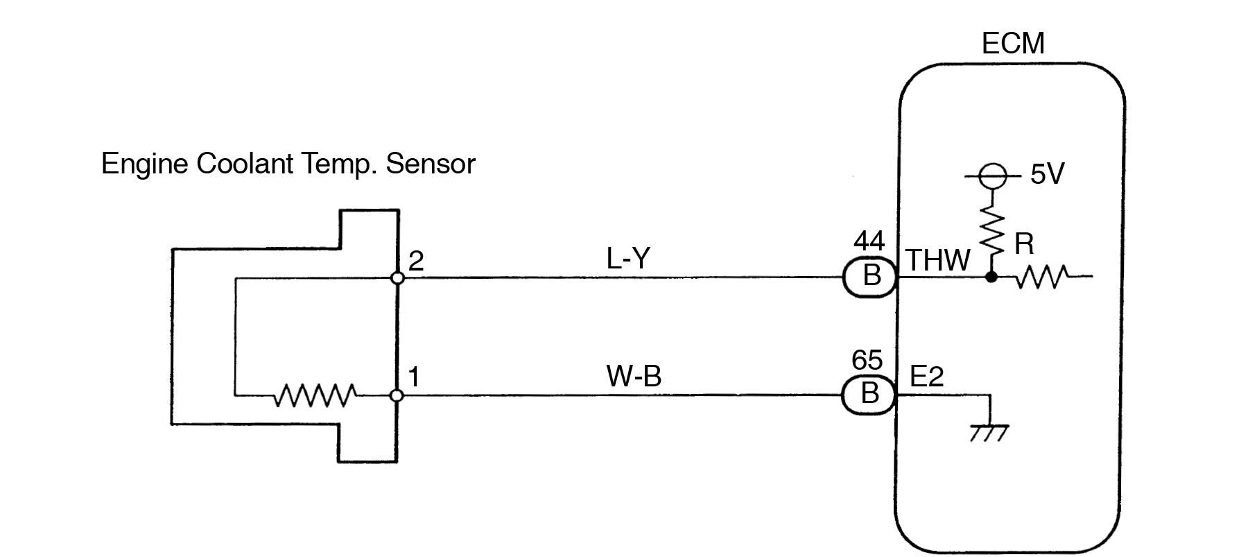
In a 2-wire CTS setup, you'll typically see two wires:
- Reference Voltage Wire: Supplies the 5V reference voltage from the ECU to the CTS.
- Signal Return Wire: Returns the voltage signal from the CTS to the ECU. The ECU measures the voltage on this wire to determine the coolant temperature.
How It Works: The Electrical Circuit
The 2-wire CTS works as a simple voltage divider circuit. The ECU provides a 5V reference voltage through a resistor (often internal to the ECU) and then to the CTS. The CTS, being a thermistor, acts as a variable resistor in series with the ECU's internal resistor. The voltage at the point between the ECU's resistor and the CTS changes based on the CTS's resistance. As the coolant temperature increases, the CTS resistance decreases, which causes the voltage at the signal return wire to decrease. The ECU reads this voltage and correlates it to a specific coolant temperature value using a lookup table or mathematical equation. This temperature information is used for various engine control functions, such as fuel injection, ignition timing, and cooling fan activation.
Essentially, the ECU *measures* the temperature indirectly, by measuring the voltage that changes *because* of the temperature change.
Real-World Use: Basic Troubleshooting
Let's say you're getting a P0118 code (Coolant Temperature Sensor Circuit High Input). Here's how you can use the wiring diagram to troubleshoot:
- Locate the CTS Connector: Use the diagram to pinpoint the physical location of the CTS and its connector.
- Visual Inspection: Check the connector for corrosion, damaged wires, or loose connections. Clean or repair as needed.
- Voltage Measurement: With the ignition on (engine off), use a multimeter to measure the voltage at the CTS connector. You should see close to 5V on the reference voltage wire.
- Continuity Test: Disconnect the CTS and use a multimeter to measure the resistance of the CTS itself. Compare the measured resistance to the specifications for your sensor at a known temperature (e.g., room temperature).
- Wiring Integrity Check: Use a multimeter to check the continuity of the wires between the CTS connector and the ECU connector. This verifies that there are no breaks in the wires. Also, check for shorts to ground.
- ECU Connector Inspection: Examine the ECU connector for corrosion or damaged pins. Reseat the connector and try again.
A high input code often indicates an open circuit (broken wire) or a disconnected sensor. The ECU is seeing a very high voltage (close to 5V) because the signal return wire is not being pulled down by the CTS resistance. A low input code, conversely, often suggests a short to ground.
Safety Considerations
Working with automotive electrical systems can be dangerous. Here's what to keep in mind:
- Battery Disconnect: Always disconnect the negative terminal of the battery before working on any electrical components. This prevents accidental shorts and potential damage to the electrical system.
- ECU Handling: Handle the ECU with care. Avoid static electricity and dropping it.
- Wiring Harness Integrity: Be careful not to damage the wiring harness when working around it. Avoid pulling on wires or using sharp objects near the harness.
- Hot Coolant: If the engine is hot, be extremely careful when working around the CTS. Coolant can scald you. Let the engine cool down completely before attempting any repairs.
- Component Identification: Always verify that you are working on the correct components before disconnecting or testing anything. Double-check the wiring diagram and component locations.
Risk area: The ECU is a sensitive electronic device. Improper handling or wiring can permanently damage it.
By understanding the 2-wire CTS wiring diagram, you'll gain valuable insight into your car's engine management system and be better equipped to diagnose and repair problems. Remember to always consult the specific wiring diagram for your vehicle model, as wiring configurations can vary.
We have a sample 2-wire Coolant Temperature Sensor Wiring Diagram file that can be useful for your reference. You can download the file.