2 Wire Fuel Shut Off Solenoid Wiring Diagram
Okay, let's dive into the nitty-gritty of a 2-wire fuel shut-off solenoid wiring diagram. This isn't just about lines and squiggles; it's about understanding how your engine gets its fuel supply, and how to troubleshoot issues when things go wrong. Whether you're tackling a repair, modifying your fuel system, or simply expanding your automotive knowledge, understanding this diagram is a vital skill.
Purpose of Understanding the Wiring Diagram
The fuel shut-off solenoid wiring diagram is your roadmap for diagnosing and resolving fuel-related problems. Think of it as the key to unlocking several important tasks:
- Troubleshooting Fuel Delivery Issues: If your engine is stalling, not starting, or running poorly, the solenoid might be the culprit. The diagram helps you trace the electrical path, pinpoint the fault, and test components.
- Performing Repairs & Replacements: If the solenoid or related wiring is damaged, the diagram shows you how to correctly replace components and reconnect the wiring, ensuring proper functionality.
- Modifying Fuel Systems: When upgrading or customizing your fuel system, especially on older diesel engines or carburetored setups, you'll need to understand how the solenoid interacts with other components.
- Learning About Engine Control: Even if you don't plan on diving into repairs immediately, understanding the fuel shut-off system is a great way to learn about the basics of engine control systems.
Key Specs and Main Parts
Before we dissect the diagram, let's define the key components we'll encounter:
- Fuel Shut-Off Solenoid: This is an electromagnetic valve that controls the flow of fuel to the engine. When energized, it opens, allowing fuel to pass. When de-energized, it closes, cutting off the fuel supply and stopping the engine.
- Power Source (Battery or Ignition Switch): The solenoid needs power to operate. This usually comes directly from the battery through a fused circuit or is switched on and off by the ignition switch.
- Ground Connection: A good ground connection is crucial for completing the electrical circuit. Often, the solenoid grounds directly to the engine block or chassis.
- Wiring: The wires connecting these components are crucial. Expect to see different wire gauges (thicknesses) depending on the current requirements. Typical wire gauges might range from 16 AWG to 12 AWG.
- Fuse or Circuit Breaker: Provides overcurrent protection for the solenoid circuit. A blown fuse is often a sign of a short circuit or a malfunctioning solenoid.
Symbols in the Wiring Diagram
Wiring diagrams use standardized symbols to represent components and connections. Here’s a breakdown of what you'll typically see:
- Solid Lines: Represent wires. The thickness of the line *doesn't* typically indicate wire gauge.
- Dashed Lines: Might represent shielded cables or connections behind a panel or within a harness.
- Colors: Wires are often color-coded. Common colors include red (power), black (ground), and other colors for specific signals. The diagram legend should always specify the color code.
- Solenoid Symbol: Usually a coil symbol with a line through it, often with an arrow indicating the direction of fuel flow when open.
- Battery Symbol: A series of alternating long and short parallel lines, with "+" indicating the positive terminal and "-" indicating the negative terminal.
- Ground Symbol: There are several variations, including a downward-pointing arrow, a series of stacked horizontal lines, or a chassis ground symbol (resembling an upside-down Christmas tree).
- Fuse Symbol: A zig-zag line enclosed in a rectangle or a simple line break.
- Connector Symbol: Usually represented by small circles or squares where wires connect. Numbered pins within the connector are often indicated.
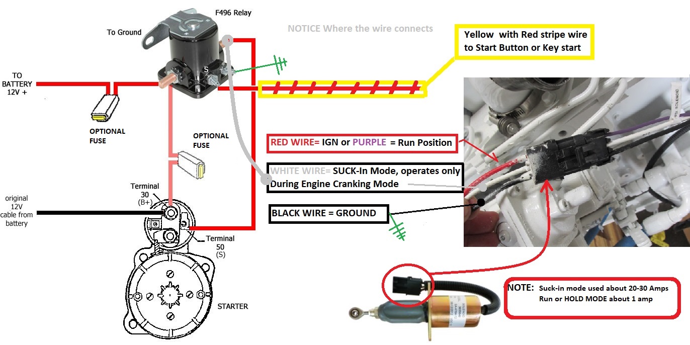
How It Works: The 2-Wire Solenoid Circuit
The 2-wire fuel shut-off solenoid is a relatively simple circuit. Here's how it generally works:
- Power Supply: When the ignition switch is turned to the "on" position (or sometimes the "run" position), power is supplied to the solenoid through a fused circuit.
- Energizing the Solenoid: The power flows through one of the solenoid's two wires, creating an electromagnetic field within the solenoid.
- Opening the Valve: This electromagnetic field pulls a plunger or other mechanism inside the solenoid, opening the fuel valve. This allows fuel to flow to the engine.
- Grounding the Circuit: The current flows out of the solenoid through the second wire, completing the circuit to ground (either through the engine block/chassis or directly to the battery's negative terminal).
- Shutting Off the Engine: When the ignition switch is turned off, the power supply to the solenoid is cut. The electromagnetic field collapses, and a spring (or other mechanism) forces the plunger to close the fuel valve, cutting off the fuel supply and stopping the engine.
Important Note: Some solenoids are designed to be normally closed (requiring power to open) while others are normally open (requiring power to close). The wiring diagram will indicate the type of solenoid used.
Real-World Use: Basic Troubleshooting
Let's say your engine won't start. Here are some troubleshooting steps using the wiring diagram:
- Check the Fuse: Use a multimeter to check the fuse for continuity. If it's blown, replace it with a fuse of the correct amperage rating. A repeated blown fuse indicates a short circuit.
- Check for Power: With the ignition switch in the "on" position, use a multimeter to check for voltage at the solenoid's power wire. If there's no voltage, trace the wiring back to the power source (ignition switch, battery) and look for breaks or loose connections.
- Check the Ground Connection: Ensure the solenoid has a good ground connection. Clean any corrosion from the ground terminal and the engine block/chassis where it connects. Use a multimeter to check for continuity between the solenoid's ground wire and the battery's negative terminal.
- Test the Solenoid: Disconnect the solenoid from the wiring harness. Apply 12V directly to the solenoid's terminals. You should hear a distinct "click" as the solenoid activates. If it doesn't click, the solenoid is likely faulty and needs replacement.
- Inspect Wiring: Visually inspect the wiring for any damage, such as frayed insulation, broken wires, or corroded connectors. Use a wire stripper and crimping tool to repair or replace damaged sections.
Safety Precautions
Working with electrical systems and fuel requires caution:
- Disconnect the Battery: Always disconnect the negative battery terminal before working on any electrical components to prevent accidental shorts.
- Fuel Hazards: Fuel is flammable. Work in a well-ventilated area and avoid sparks or open flames. Have a fire extinguisher nearby.
- Handling Fuses: Never replace a blown fuse with one of a higher amperage rating. This can overload the circuit and cause a fire.
- Wiring Harness Integrity: Be careful when working with wiring harnesses. Damaging the insulation can create short circuits.
The fuel shut off solenoid sits within the fuel system. Therefore, always take care when dismantling. It is possible to be exposed to pressurized fuel. Relieve any pressure before commencing work.
Remember: If you're not comfortable working on electrical or fuel systems, it's always best to consult a qualified mechanic. Incorrect repairs can lead to further damage or even safety hazards.
Now that you have a better understanding of the 2-wire fuel shut-off solenoid wiring diagram, you're better equipped to diagnose and repair fuel system problems. To further assist you, we have a detailed downloadable wiring diagram available. This resource will provide you with visual support, connector pinout information, and step-by-step instructions to facilitate more informed troubleshooting.