
2 Wire Ignition Coil Diagram Motorcycle
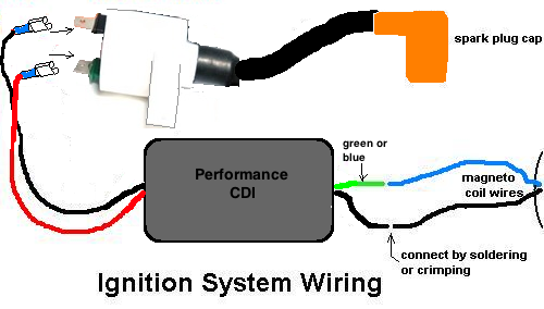
Understanding the 2-wire ignition coil diagram for your motorcycle is crucial whether you're troubleshooting a no-start condition, performing routine maintenance, or even planning a custom modification. This guide will break down the essentials, assuming you have some experience working with automotive electrical systems. We'll cover the key components, how the system functions, basic troubleshooting tips, safety precautions, and how to interpret the diagram itself.
Purpose of Understanding the 2-Wire Ignition Coil Diagram
The ignition coil is a vital component in your motorcycle's ignition system. A thorough understanding of its wiring diagram is essential for several reasons:
- Troubleshooting Starting Problems: When your motorcycle refuses to start, the ignition system is often the prime suspect. The diagram helps you pinpoint the problem, whether it's a faulty coil, wiring issue, or problem with the trigger signal.
- Performing Maintenance and Repairs: The diagram is an invaluable reference when replacing the ignition coil, checking wiring connections, or diagnosing other ignition-related problems.
- Custom Modifications: If you're planning any modifications to your motorcycle's electrical system, such as installing a new CDI (Capacitive Discharge Ignition) unit or upgrading the ignition coil, the diagram provides the necessary information to ensure proper connections and avoid damaging the system.
- General Understanding of Motorcycle Electrics: Even if you're not currently experiencing any problems, understanding the ignition system helps you grasp the fundamentals of motorcycle electrics and empowers you to perform more complex repairs and modifications in the future.
Key Specs and Main Parts of a 2-Wire Ignition System
A basic 2-wire ignition system is relatively simple, relying on just a few key components:
- Ignition Coil: The heart of the system. It's a transformer that steps up the low voltage from the battery to a high voltage (typically thousands of volts) necessary to create a spark at the spark plug.
- Spark Plug: The device that delivers the high-voltage spark to the combustion chamber, igniting the air-fuel mixture.
- Primary Winding: The low-voltage winding of the ignition coil. It receives the initial current from the motorcycle's electrical system.
- Secondary Winding: The high-voltage winding of the ignition coil. It's connected to the spark plug and delivers the high-voltage spark.
- Trigger/Pickup Coil (or Points): Generates a signal that tells the CDI unit (or points-based system) when to fire the ignition coil. This signal is crucial for timing the spark properly. In simpler systems, this may be a set of contact points that open and close.
- CDI Unit (Capacitive Discharge Ignition) or Points-Based System: The electronic control unit that controls the charging and discharging of the capacitor, triggering the ignition coil to fire. In older motorcycles, this function is performed by a set of mechanical contact points.
- Kill Switch: A safety switch that interrupts the power supply to the ignition system, preventing the motorcycle from starting.
Key Specs to Consider:
- Primary Resistance: Measured in ohms (Ω), this is the resistance of the primary winding. It's important for proper current flow.
- Secondary Resistance: Also measured in ohms (Ω), this is the resistance of the secondary winding. It's much higher than the primary resistance.
- Output Voltage: Measured in kilovolts (kV), this is the maximum voltage the coil can produce.
Understanding the Symbols in a 2-Wire Ignition Coil Diagram
Electrical diagrams use standardized symbols to represent components and connections. Understanding these symbols is vital for interpreting the diagram correctly.
- Straight Lines: Represent wires. Thicker lines may indicate higher current-carrying capacity.
- Dots at Wire Junctions: Indicate that wires are connected. If two lines cross without a dot, they are *not* connected.
- Zigzag Line: Represents a resistor. In this context, it could represent the internal resistance of the coil windings.
- Coil Symbol (Curly Line): Represents the ignition coil itself. The primary and secondary windings may be shown as separate coils within the symbol.
- Ground Symbol (Usually Three Descending Lines): Indicates a connection to the chassis ground, which is the negative terminal of the battery.
- Battery Symbol (Alternating Long and Short Lines): Represents the battery, the power source for the system.
- Switch Symbol: Represents a switch, such as the ignition switch or kill switch.
Color Coding: Color coding of wires is often included in the diagram. Common colors include:
- Red: Typically indicates a positive (+) power wire.
- Black: Typically indicates a ground (-) wire.
- Other Colors: Other colors (e.g., blue, green, yellow) are used for signal wires or wires connecting to specific components. Always refer to the diagram's legend for the specific color code used.
How a 2-Wire Ignition System Works
The basic principle of a 2-wire ignition system is electromagnetic induction. Here's a breakdown of the process:
- Power Supply: The system receives power from the motorcycle's battery.
- Primary Circuit: When the ignition switch is turned on, current flows through the primary winding of the ignition coil.
- Triggering Event: The trigger signal (from the pickup coil or points) interrupts the current flow in the primary winding. In a CDI system, the CDI unit controls this interruption. In a points system, the points open and close, interrupting the current flow.
- Magnetic Field Collapse: When the current flow is interrupted, the magnetic field around the primary winding collapses rapidly.
- Voltage Induction: This rapid collapse of the magnetic field induces a high voltage in the secondary winding of the ignition coil. The ratio of turns between the primary and secondary windings determines the voltage amplification.
- Spark Generation: The high voltage from the secondary winding is sent to the spark plug, where it creates a spark across the spark plug gap, igniting the air-fuel mixture in the combustion chamber.
Real-World Use: Basic Troubleshooting Tips
Here are some basic troubleshooting steps you can take using the 2-wire ignition coil diagram:
- No Spark: If you're not getting a spark at the spark plug:
- Check the Spark Plug: Make sure the spark plug is clean and properly gapped.
- Check the Coil: Use a multimeter to measure the resistance of the primary and secondary windings. Compare your readings to the specifications for your coil. An open circuit (infinite resistance) indicates a faulty winding.
- Check the Wiring: Inspect the wiring connections to the ignition coil and spark plug for corrosion, loose connections, or damaged wires. Use the diagram to trace the wiring.
- Check the Trigger Signal: Use a multimeter or oscilloscope to check for a trigger signal from the pickup coil or points. If there's no signal, the pickup coil or points may be faulty.
- Check the Kill Switch: Ensure the kill switch is in the "run" position.
- Weak Spark: If you're getting a weak spark:
- Check the Coil: As above, check the resistance of the coil windings.
- Check the Battery Voltage: A low battery voltage can reduce the spark intensity.
- Check for Shorts: Look for any signs of shorts to ground in the wiring.
Safety Precautions
Working with the ignition system involves potentially dangerous high voltages. Take the following precautions:
- Disconnect the Battery: Before working on any electrical components, disconnect the negative terminal of the battery to prevent accidental shocks or damage to the electrical system.
- Use Insulated Tools: Use tools with insulated handles to minimize the risk of electric shock.
- Avoid Touching Exposed Wires: Never touch exposed wires or terminals when the ignition system is powered on.
- Discharge Capacitors (if applicable): If your motorcycle has a CDI unit, be aware that the capacitor can store a high voltage even after the ignition is turned off. Consult your service manual for instructions on how to safely discharge the capacitor before working on the CDI unit.
High-voltage components, such as the ignition coil and spark plug wire, can deliver a potentially lethal shock. Always exercise extreme caution when working with these components.
Remember, proper diagnosis and repair often require specialized tools and expertise. If you're not comfortable working on the ignition system yourself, it's always best to consult a qualified motorcycle mechanic.
We have a detailed 2-Wire Ignition Coil Diagram file available for download. This diagram includes specific color codes and component locations for various common motorcycle models. This resource will be invaluable in your troubleshooting and repair endeavors. Contact us to request access to the file.