2 Wire Speed Sensor Wiring Diagram
Understanding the 2-Wire Speed Sensor Wiring Diagram is crucial for a variety of automotive tasks, ranging from diagnosing sensor failures to performing custom modifications on your vehicle. Whether you're troubleshooting a faulty speedometer, installing an aftermarket control system, or simply seeking to deepen your understanding of automotive electronics, this guide will provide you with the knowledge needed to confidently interpret and utilize these diagrams.
Purpose of Understanding the 2-Wire Speed Sensor Wiring Diagram
The primary purpose of understanding this diagram extends far beyond simply knowing where to connect wires. It empowers you to:
- Diagnose Sensor Problems: Identify breaks, shorts, or other issues in the wiring that can cause inaccurate speed readings or complete sensor failure.
- Perform Accurate Repairs: Replace damaged wiring or connectors correctly, ensuring proper signal transmission.
- Install Aftermarket Components: Integrate new speed-sensitive devices, such as electronic speed controllers (ESCs) or data loggers, seamlessly into your vehicle's system.
- Gain a Deeper Understanding: Develop a more comprehensive understanding of your vehicle's electronic systems, leading to more informed maintenance and modification decisions.
Key Specs and Main Parts
Before diving into the diagram itself, let's define the core components and specifications involved:
- Speed Sensor: The heart of the system, responsible for converting wheel speed (or transmission output shaft speed) into an electrical signal. Typically, this is a variable reluctance sensor (VRS) or a Hall-effect sensor.
- Wiring Harness: The network of wires that connect the speed sensor to the Engine Control Unit (ECU) or other relevant control module.
- Connectors: The physical interfaces that allow you to plug and unplug the sensor and harness. Pay close attention to pinout configurations.
- ECU (Engine Control Unit): The central processing unit that receives the speed signal and uses it for various functions, including speedometer display, cruise control operation, and traction control.
- Power Source (Typically 5V or 12V): Hall-effect sensors usually require a voltage supply to operate, while VRS sensors generate their own voltage based on the changing magnetic field. The wiring diagram specifies the voltage levels.
- Ground: Provides a return path for the electrical current.
- Signal Wire: Carries the speed signal from the sensor to the ECU.
Important Specifications:
- Voltage Range: Know the expected voltage range of the signal wire. This is critical for diagnostics.
- Resistance: The internal resistance of the sensor coil (for VRS sensors) is an important diagnostic parameter.
- Frequency Range: The frequency of the signal varies with speed. Knowing the expected frequency range at different speeds can aid in troubleshooting.
Symbols Explained: Decoding the Diagram
Understanding the symbols used in a 2-Wire Speed Sensor Wiring Diagram is paramount. Here’s a breakdown of common elements:
- Solid Lines: Represent wires. The thickness of the line usually doesn't indicate anything specific, but it's consistent throughout the diagram.
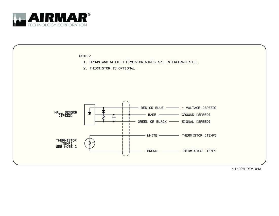
- Dashed Lines: Often represent shielded wiring, indicating a cable designed to minimize electromagnetic interference (EMI). Shielded wires typically have a ground connection.
- Colors: Each wire is assigned a color code (e.g., RED, BLK, GRN) to aid in identification. Color codes are standardized but can vary slightly between manufacturers. Refer to the diagram's legend.
- Connectors: Represented by various shapes (circles, squares, rectangles) with numbers indicating pin assignments. Understanding the connector pinout is critical.
- Ground Symbol: Typically a series of horizontal lines decreasing in length, connected to ground connections.
- Sensor Symbol: The sensor symbol varies based on the sensor type (VRS or Hall-effect). VRS sensors may look like a coil, while Hall-effect sensors are often depicted as a rectangle with input and output lines.
- Resistor Symbol: A jagged line represents a resistor. Some circuits use pull-up or pull-down resistors.
Example:
A line labeled "RED/WHT" means the wire is red with a white stripe. Following this line to its connector will show you which pin the wire should be connected to.
How It Works: From Wheel Rotation to ECU Input
The fundamental principle is to convert mechanical motion (wheel rotation) into an electrical signal the ECU can interpret. Here's a simplified explanation:
- VRS Sensor Operation: As the toothed wheel (reluctor ring) attached to the rotating component (wheel hub or transmission output shaft) passes the VRS sensor, it alters the magnetic field. This changing magnetic field induces an AC voltage in the sensor coil. The frequency and amplitude of this AC voltage are directly proportional to the speed of rotation.
- Hall-Effect Sensor Operation: Hall-effect sensors require an external power supply (typically 5V or 12V). A rotating toothed wheel passes by the sensor. The presence of a tooth or the absence of a tooth causes a change in the magnetic field detected by the Hall-effect sensor. This change in magnetic field alters the output voltage of the sensor, creating a digital signal (high/low voltage) that corresponds to the rotational speed.
- Signal Transmission: The sensor's electrical signal is then transmitted through the wiring harness to the ECU.
- ECU Interpretation: The ECU processes the signal to determine the vehicle speed. This information is used for various functions, including speedometer display, cruise control, ABS, traction control, and engine management.
Real-World Use: Basic Troubleshooting Tips
Here's how you can use your understanding of the wiring diagram to troubleshoot common speed sensor issues:
- No Speedometer Reading: Check the wiring and connectors for damage or corrosion. Use a multimeter to verify continuity between the sensor and the ECU. Inspect the sensor itself for physical damage. Measure the resistance of a VRS sensor coil. Verify the presence of power (typically 5V or 12V) and ground to a Hall effect sensor.
- Intermittent Speedometer Reading: Look for loose connections, damaged wiring (especially where wires flex), or a failing sensor. Vibration can exacerbate these problems.
- Incorrect Speedometer Reading: This could be caused by a faulty sensor, incorrect wiring, or a problem with the ECU. Double-check the wiring connections against the diagram. If you have recently changed tire sizes or gear ratios, the ECU may need to be recalibrated.
- ABS or Traction Control Issues: Speed sensor data is critical for ABS and traction control. Problems with the speed sensor can trigger warning lights and disable these systems.
Troubleshooting Steps:
- Visual Inspection: Check the wiring and connectors for any obvious signs of damage.
- Continuity Test: Use a multimeter to check the continuity of the wires between the sensor and the ECU.
- Voltage Test: Verify that the sensor is receiving the correct voltage (if applicable).
- Resistance Test: Measure the resistance of the sensor coil (VRS sensor).
- Signal Verification: Use an oscilloscope to view the signal from the sensor while the wheels are rotating. This can help identify signal dropouts or other anomalies.
Safety Considerations
Working with automotive electrical systems can be dangerous. Always observe the following safety precautions:
- Disconnect the Battery: Before working on any electrical components, disconnect the negative terminal of the battery to prevent accidental shorts and electrical shock.
- Identify High-Current Circuits: Be aware of circuits that carry high current, such as the starter motor circuit. Avoid working on these circuits unless you have the necessary expertise and equipment.
- Use Proper Tools: Use insulated tools specifically designed for automotive electrical work.
- Avoid Working in Wet Conditions: Water can conduct electricity, increasing the risk of electrical shock.
- Component Temperature: Some components, such as the exhaust system and engine, can become extremely hot. Allow these components to cool down before working near them.
- Airbag System: The airbag system is a delicate, potentially explosive system. Be extremely careful when working near any airbag components. Refer to your vehicle's service manual for specific safety precautions.
Disclaimer: This guide provides general information and should not be considered a substitute for professional automotive repair advice. Always consult a qualified mechanic if you are unsure about any aspect of automotive repair.
We have a detailed 2-Wire Speed Sensor Wiring Diagram file available for download. This diagram provides a visual aid to help you understand how the sensor is connected to the vehicle's electrical system. The diagram includes wire colors, connector locations, and pin numbers, making it easier to troubleshoot and repair any issues with the speed sensor.