2 Wire Temp Sensor Wiring Diagram
So, you're looking to understand the ins and outs of a 2-wire temperature sensor wiring diagram? Excellent! Whether you're diagnosing a faulty sensor, adding a temperature gauge to your project car, or simply trying to deepen your understanding of automotive electronics, knowing how these sensors are wired is crucial. We're here to break it down for you in a clear, concise way.
Purpose of Understanding 2-Wire Temperature Sensor Wiring Diagrams
Why bother with this diagram in the first place? Well, having a solid understanding lets you:
- Troubleshoot accurately: Pinpoint the source of a temperature-related issue, instead of blindly replacing parts.
- Perform repairs confidently: Fix broken wires, replace connectors, or even replace the sensor yourself.
- Upgrade your vehicle: Add aftermarket temperature gauges, sensors, or controllers for improved performance monitoring.
- Expand your knowledge: Grasp the fundamental principles of automotive electrical systems.
Key Specifications and Main Parts
Before diving into the diagram itself, let's cover the key components involved:
- Temperature Sensor: This is the heart of the system. It's a device that changes its electrical resistance based on temperature. These are typically thermistors or resistance temperature detectors (RTDs). A thermistor is a type of resistor whose resistance varies significantly with temperature. RTDs are similar, but typically use platinum and offer better accuracy and stability. In a 2-wire sensor, one wire provides the power/signal and the other serves as the return/ground.
- Wiring Harness: This is a bundle of wires that connects the sensor to the Engine Control Unit (ECU) or other control module. It protects the wires and ensures a reliable connection.
- Connectors: These provide a secure and weatherproof connection between the sensor and the wiring harness.
- ECU/Control Module: This is the "brain" of the system. It reads the signal from the temperature sensor, interprets the temperature value, and uses this information to control various engine functions (fuel injection, ignition timing, etc.).
- Power Source: Typically a 5V or 12V reference voltage provided by the ECU or another control module.
Symbols in a 2-Wire Temperature Sensor Wiring Diagram
Wiring diagrams use a standardized set of symbols to represent electrical components and connections. Let's decode the ones you'll encounter in a 2-wire temperature sensor diagram:
- Straight Lines: Represent wires. Thicker lines may indicate a larger wire gauge.
- Dashed Lines: Often indicate shielded wires, used to prevent electrical noise from interfering with the sensor signal.
- Colored Lines: Indicate the color of the wire insulation. Common colors include red (power), black (ground), and various colors for signal wires (e.g., blue, green, yellow). Understanding wire colors is extremely helpful during troubleshooting.
- Circles or Squares with Numbers or Letters: Represent connector pins. The numbers or letters correspond to the pin designations on the connector.
- Resistor Symbol: A zigzag line representing the thermistor within the temperature sensor.
- Ground Symbol: A symbol resembling a downward-pointing tree or an inverted pyramid, indicating a connection to the vehicle's chassis ground.
- ECU Symbol: Usually a rectangular box with pins labeled for input/output signals.
A typical diagram might look something like this (imagine the ASCII art as proper drawing):
       +5V (or 12V)
         |
         |
        [Resistor] <--- Pull-up resistor within the ECU
         |
         |
      +-------+
      |       |
      |  Sensor |
      |       |
      +-------+
         |
         |
        GND
How It Works
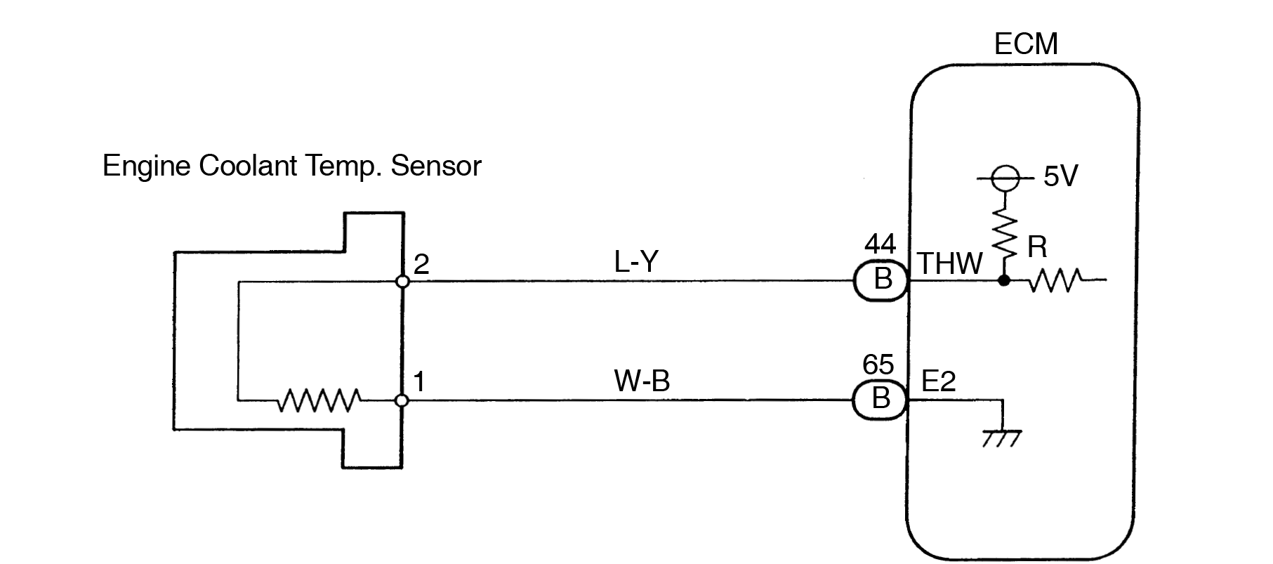
The 2-wire temperature sensor operates on a simple principle: as temperature changes, the resistance of the thermistor changes. This resistance change affects the voltage at the input pin of the ECU. Here’s the breakdown:
- The ECU provides a reference voltage (typically 5V or 12V) to one side of the temperature sensor, often through a "pull-up" resistor located inside the ECU. This pull-up resistor is crucial. Without it, the ECU wouldn't be able to detect changes in the sensor's resistance.
- The other side of the sensor is connected to ground (GND).
- As the temperature increases, the resistance of the thermistor decreases (for Negative Temperature Coefficient - NTC thermistors, which are most common).
- This decreased resistance allows more current to flow through the circuit, resulting in a lower voltage at the ECU's input pin.
- The ECU monitors this voltage change and correlates it to a specific temperature value using a pre-programmed lookup table or formula.
In essence, the temperature sensor acts as a variable resistor, and the ECU interprets the voltage drop across it to determine the temperature.
Real-World Use: Basic Troubleshooting Tips
Okay, your check engine light is on, and you suspect a temperature sensor issue. Here's how you can use your knowledge of the wiring diagram to troubleshoot:
- Check for Obvious Damage: Start by visually inspecting the sensor, wiring harness, and connectors for any signs of damage (broken wires, corroded connectors, etc.).
- Use a Multimeter:
- Voltage Test: With the ignition on (but engine off), use a multimeter to check the voltage at the sensor connector. You should see a voltage close to the reference voltage (e.g., 5V). If the voltage is significantly lower or zero, there may be a problem with the wiring or the ECU's power supply.
- Resistance Test: Disconnect the sensor from the wiring harness. Use a multimeter to measure the resistance across the sensor's terminals. Compare this resistance value to the sensor's specification at a known temperature (you'll need the sensor's data sheet for this). An unusually high or low resistance reading indicates a faulty sensor.
- Continuity Test: Use a multimeter to check the continuity of the wires between the sensor connector and the ECU connector. A lack of continuity indicates a broken wire.
- Scan for Diagnostic Trouble Codes (DTCs): Use an OBD-II scanner to retrieve any diagnostic trouble codes related to the temperature sensor. These codes can provide valuable clues about the nature of the problem. Common codes include:
P0116: Engine Coolant Temperature Circuit Range/Performance
P0117: Engine Coolant Temperature Circuit Low Input
P0118: Engine Coolant Temperature Circuit High Input - Check the Ground Connection: A poor ground connection can cause inaccurate readings. Ensure the ground wire is securely connected to the vehicle's chassis ground.
Safety Considerations
Working with automotive electrical systems involves certain risks. Keep these safety precautions in mind:
- Disconnect the Battery: Before working on any electrical components, disconnect the negative terminal of the battery to prevent accidental shorts or electric shocks.
- Use Proper Tools: Use insulated tools to avoid electrical shock.
- Be Aware of Hot Components: Be careful when working near hot engine components (e.g., exhaust manifold, coolant hoses).
- High Energy Circuits: The ECU itself, and any modules containing capacitors can hold a charge even after the battery is disconnected. Allow time for discharge.
- Follow Wiring Diagrams Carefully: Double-check your connections to avoid wiring errors. Wiring something incorrectly can damage the ECU or other electrical components.
Remember that some components within the ECU, especially capacitors, can store a charge even after the battery is disconnected. Handle these components with care to avoid electric shock. It's always best to consult a qualified technician if you're unsure about any aspect of the repair.
We have a detailed 2-wire temperature sensor wiring diagram available for download. This diagram includes color-coded wiring and pinout information for common sensor types. We believe this diagram will serve as a valuable resource as you troubleshoot your vehicle. You can download it [HERE - Link to Downloadable Diagram]. Remember to always practice safe working habits when dealing with automotive electrical systems.