
2000 Chevy Silverado Ac System Diagram
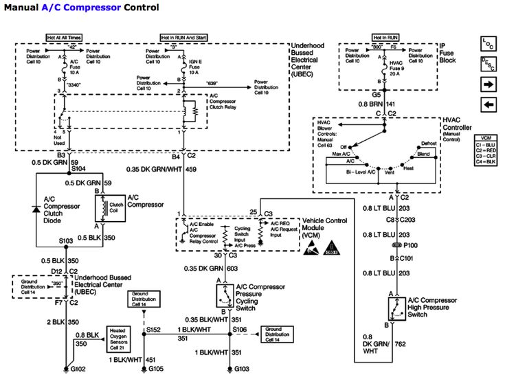
Hey folks, let's dive into the air conditioning system of the 2000 Chevy Silverado. Understanding how your AC works is crucial, whether you're tackling a repair yourself, modifying your truck, or just expanding your automotive knowledge. This deep dive, aided by the AC system diagram, will give you the confidence to diagnose issues and potentially save a bundle on mechanic's fees.
Purpose of the AC System Diagram
The AC system diagram is essentially a roadmap of your truck's cooling system. It shows the physical layout of the components, their connections, and the flow of refrigerant. Why is this important? Because with this diagram, you can:
- Troubleshoot AC problems: Identify the location of a leak, a faulty sensor, or a blockage.
- Perform Repairs: Replace a specific component without disturbing the rest of the system.
- Understand the System: Learn how each part contributes to the cooling process.
- Plan Modifications: If you're considering upgrading your AC system or adding auxiliary cooling, the diagram will be invaluable.
Key Specs and Main Parts of the 2000 Silverado AC System
The 2000 Silverado typically used R-134a refrigerant. R-134a is a hydrofluorocarbon (HFC) refrigerant used in many vehicle AC systems. The typical refrigerant charge for a 2000 Silverado is around 32 ounces, but always check the sticker under the hood for the exact specification for your vehicle. Here’s a breakdown of the main components:
- Compressor: The heart of the system. Driven by the engine, the compressor increases the pressure and temperature of the refrigerant vapor. It uses a clutch (an electromagnetic on/off switch) to engage and disengage the cooling system.
- Condenser: Located at the front of the truck (usually near the radiator), the condenser cools the high-pressure, high-temperature refrigerant vapor, turning it into a high-pressure liquid. It's basically a small radiator for the refrigerant.
- Receiver-Drier (or Accumulator): This component filters the refrigerant and removes moisture. It also acts as a reservoir for liquid refrigerant. The accumulator is used in systems with an orifice tube, while the receiver-drier is used in systems with a thermal expansion valve (TXV). The 2000 Silverado typically uses an Accumulator.
- Orifice Tube (or Thermal Expansion Valve - TXV): The orifice tube is a fixed-size restrictor that meters the flow of refrigerant into the evaporator. The TXV, on the other hand, is a more sophisticated valve that adjusts the refrigerant flow based on the evaporator temperature. The 2000 Silverado uses an Orifice Tube.
- Evaporator: Located inside the HVAC (Heating, Ventilation, and Air Conditioning) box in the dashboard, the evaporator is where the refrigerant absorbs heat from the cabin air, causing the air to cool down. The refrigerant boils and becomes a low-pressure vapor.
- Hoses and Lines: These connect all the components and carry the refrigerant throughout the system. They can be made of rubber or metal.
- Pressure Switches: These safety devices monitor the refrigerant pressure. They can shut off the compressor if the pressure is too high or too low, preventing damage to the system. A high-pressure switch and a low-pressure switch are common.
Understanding the Symbols on the Diagram
The AC system diagram uses a standardized set of symbols to represent the different components and their connections. Here’s a general overview:
- Lines: Solid lines usually represent refrigerant lines. Dotted lines may represent electrical wiring or vacuum lines.
- Colors: While not always present, different colors may be used to indicate high-pressure vs. low-pressure lines, or different refrigerant temperatures. Refer to the legend on your specific diagram.
- Component Icons: Each component has a specific icon, such as a zigzag line for the evaporator, a coil symbol for the condenser, and a pump symbol for the compressor. The diagram legend will explain each symbol.
- Arrows: Indicate the direction of refrigerant flow.
How the AC System Works
Here's a simplified explanation of the refrigeration cycle:
- Compression: The compressor takes in low-pressure, low-temperature refrigerant vapor and compresses it, raising its pressure and temperature.
- Condensation: The high-pressure, high-temperature refrigerant vapor flows to the condenser, where it releases heat to the outside air and condenses into a high-pressure, high-temperature liquid.
- Metering: The high-pressure liquid refrigerant flows through the orifice tube, which restricts the flow and causes a pressure drop. This creates a mixture of liquid and vapor refrigerant.
- Evaporation: The low-pressure mixture of liquid and vapor refrigerant enters the evaporator, where it absorbs heat from the cabin air. As the refrigerant absorbs heat, it boils and turns into a low-pressure, low-temperature vapor. This cools the air blowing through the evaporator fins into the cabin.
- Repeat: The low-pressure, low-temperature refrigerant vapor returns to the compressor, and the cycle repeats.
Real-World Use: Basic Troubleshooting Tips
Let's say your 2000 Silverado's AC isn't blowing cold air. Here's how you can use the diagram to start troubleshooting:
- Check the Compressor Clutch: With the engine running and the AC turned on, listen for the compressor clutch to engage (you should hear a click). If the clutch isn't engaging, check the fuse and relay for the AC compressor. The diagram will show you the location of these components. If the fuse and relay are good, the problem could be a faulty compressor, a bad pressure switch, or a wiring issue.
- Check for Leaks: Look for signs of refrigerant leaks around the compressor, condenser, evaporator, and hoses. Oily residue is a good indicator of a leak. The diagram can help you pinpoint the location of these components.
- Check the Pressure Switches: Use a multimeter to test the pressure switches. The diagram will show you where they are located. If a pressure switch is faulty, it may be preventing the compressor from engaging.
- Check the Orifice Tube: A clogged orifice tube can restrict refrigerant flow and cause poor cooling. The diagram will show you the location of the orifice tube.
Safety Precautions
Working on an AC system can be dangerous. Here are some crucial safety tips:
- Refrigerant is Dangerous: Refrigerant can cause frostbite if it comes into contact with your skin or eyes. Wear safety glasses and gloves when working with the system.
- High Pressure: The AC system operates under high pressure. Do not disconnect any components while the system is pressurized. Always have the system professionally evacuated before disconnecting any lines.
- Proper Disposal: Never release refrigerant into the atmosphere. It's harmful to the environment and illegal. Have the refrigerant recovered by a certified technician.
- Electrical Hazards: Be aware of electrical components, such as the compressor clutch and pressure switches. Disconnect the battery before working on any electrical components.
Disclaimer: This information is for educational purposes only and should not be considered a substitute for professional advice. Always consult a qualified mechanic for any AC system repairs. This guide provides simplified information. Always consult your vehicle's service manual for specific instructions and torque specifications.
We have the complete 2000 Chevy Silverado AC System Diagram file readily available. It's a valuable resource for anyone working on their AC system. If you want this useful document, just reach out, and we'll get it to you.