2000 Chevy Silverado Wiring Diagram Color Code
Understanding the 2000 Chevy Silverado wiring diagram, especially the color code, is crucial for a variety of reasons, ranging from performing basic repairs to undertaking complex modifications. Whether you're tracing a short circuit, installing an aftermarket stereo, or diagnosing a sensor malfunction, knowing how to interpret the wiring diagram can save you time, money, and potential frustration. This guide will provide a detailed overview of the 2000 Silverado wiring diagram's color code and its application, empowering you to tackle electrical projects with confidence.
Purpose of the Wiring Diagram
The primary purpose of a wiring diagram is to provide a visual representation of the electrical system of your 2000 Chevy Silverado. Think of it as a roadmap for electrons. It outlines the various circuits, components, and their interconnections. Specifically, understanding the color codes helps with:
- Diagnosis: Identifying faulty wires or components by tracing circuits.
- Repair: Accurately replacing damaged wiring and connectors.
- Modification: Safely adding or altering electrical components (e.g., lights, stereo systems, alarms).
- Learning: Gaining a deeper understanding of your vehicle's electrical system.
Key Specs and Main Parts
Before diving into the color codes, let's establish some context. The 2000 Chevy Silverado wiring diagram is complex, covering a wide range of systems. Key systems include:
- Starting and Charging System: Battery, alternator, starter, and related wiring.
- Ignition System: Ignition coil(s), distributor (if applicable), spark plugs, and wiring.
- Fuel System: Fuel pump, injectors, sensors (e.g., oxygen sensors, fuel pressure sensor), and wiring.
- Lighting System: Headlights, taillights, turn signals, interior lights, and wiring.
- Body Electrical: Power windows, door locks, mirrors, and related wiring.
- Engine Control System (ECS): Engine control module (ECM), various sensors (e.g., mass airflow sensor, throttle position sensor, crankshaft position sensor), actuators (e.g., idle air control valve), and wiring. This is often the most complex part of the diagram.
- Transmission Control System (TCS): Transmission control module (TCM) for automatic transmissions, sensors, and wiring.
- Braking System: Anti-lock braking system (ABS) components, sensors, and wiring.
- Instrument Panel: Gauges, warning lights, and associated wiring.
The diagram itself typically consists of multiple pages or sections, each dedicated to a specific system or group of systems. It's essential to consult the correct section for the circuit you're working on.
Symbols: Lines, Colors, and Icons
Wiring diagrams use a standardized set of symbols and conventions. Understanding these is crucial for accurate interpretation:
- Lines: Represent wires. The thickness of the line generally doesn't indicate wire gauge, so don't read too much into it.
- Colors: The most critical element. Each color represents a unique wire and its function. We will deep dive into the color codes below.
- Icons: Represent electrical components such as:
- Resistors: Zigzag line.
- Capacitors: Two parallel lines.
- Diodes: Triangle pointing to a line.
- Relays: Coil and switch contacts.
- Fuses: S-shaped line within a rectangle.
- Switches: Various symbols depending on the type of switch (e.g., SPST, SPDT, DPDT).
- Grounds: Typically represented by a triangle pointing downwards or a series of parallel lines diminishing in size.
- Connectors: Circles or squares indicating where wires connect to other wires or components.
- Numbers/Letters: Often placed near wires or components to indicate wire gauge, circuit number, or component identification.
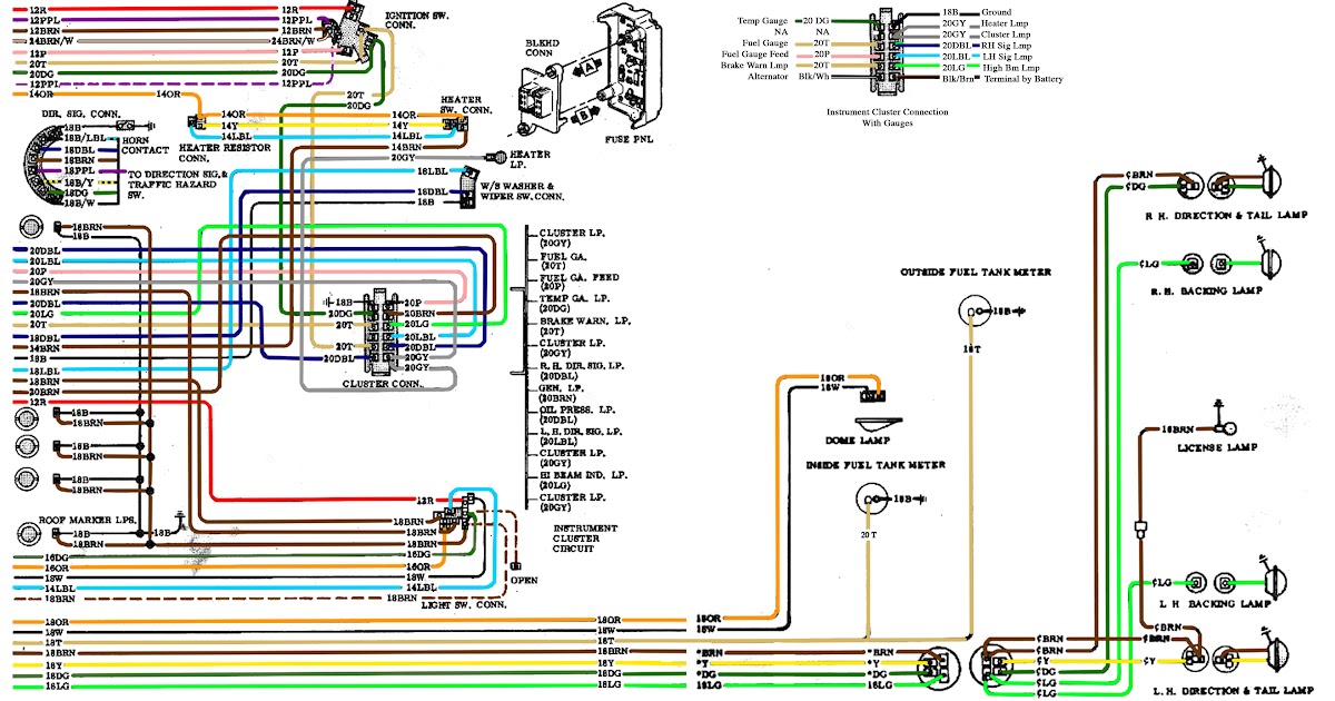
The Color Code: Decoding the Wires
The 2000 Chevy Silverado wiring diagram uses a standardized color code system. Here's a breakdown of common colors and their typical functions:
- BLK (Black): Ground – Provides a return path for current to the battery. Critical for proper circuit operation.
- RED (Red): Battery Power – Usually directly connected to the battery or a fused power source.
- ORG (Orange): Battery Power – Similar to red, but often used for different circuits or components.
- PNK (Pink): Ignition Power – Power supplied when the ignition switch is in the "run" or "start" position.
- YEL (Yellow): Ignition Power or Switched Power – Similar to pink, but could also be used for circuits controlled by other switches.
- GRN (Green): Various Functions – Often used for signals to and from sensors or control modules. Check the specific circuit to determine its exact function.
- BLU (Blue): Various Functions – Similar to green, requiring circuit-specific identification.
- WHT (White): Various Functions – Again, check the specific circuit. May be used for sensor signals or control module outputs.
- BRN (Brown): Lighting Circuits – Often used for parking lights, tail lights, or side marker lights.
- GRY (Gray): Lighting Circuits or Sensor Signals – Can be used in lighting systems or for transmitting data from sensors.
- TAN (Tan): Sensor Signals – Common for sensor circuits, especially those related to the engine control system.
Important Note: Many wires will have a primary color and a stripe color (e.g., BLK/WHT indicates a black wire with a white stripe). This provides even more specific identification.
How It Works: Tracing a Circuit
Let's say you want to trace the circuit for the driver's side power window. Here's a general approach:
- Locate the Relevant Diagram: Find the section of the wiring diagram that covers power windows.
- Identify the Power Source: Locate the fuse or circuit breaker that supplies power to the power window circuit. Note the wire color leading from the fuse box.
- Trace the Wire: Follow the colored line from the fuse box to the power window switch. The diagram will show any connectors or splices along the way.
- Follow the Signal Wires: From the power window switch, trace the wires that control the window motor. These wires will typically change polarity depending on whether you're raising or lowering the window.
- Locate the Ground: Identify the ground wire for the power window motor. This wire will typically be black and connected to a ground point on the vehicle's chassis.
Real-World Use: Basic Troubleshooting Tips
Using the wiring diagram and color codes can greatly simplify troubleshooting electrical issues. Here are some basic tips:
- No Power: If a component isn't working, use a multimeter to check for voltage at the power supply wire (e.g., red or orange). If there's no voltage, check the fuse or circuit breaker.
- Ground Fault: If a circuit is constantly blowing fuses, there might be a short to ground. Use the wiring diagram to identify potential areas where the power wire could be rubbing against the chassis.
- Open Circuit: If a circuit is dead and the fuse is good, there might be an open circuit (a break in the wire). Use a multimeter to check for continuity between different points in the circuit.
- Component Failure: The wiring diagram can help you isolate whether the problem is in the wiring or the component itself. By testing for voltage and ground at the component's connector, you can determine if the component is receiving power and ground.
When troubleshooting, remember to be methodical and patient. Start with the simplest checks and work your way up to more complex diagnoses.
Safety: Highlight Risky Components
Working with automotive electrical systems can be dangerous. Always disconnect the negative battery cable before working on any electrical components. This prevents accidental shorts and potential electrocution. Be especially careful when working with the following:
- Airbag System: The airbag system contains explosive components. Incorrect handling can cause accidental deployment, resulting in serious injury. Consult a qualified technician before working on any airbag-related wiring.
- ABS System: The ABS system also contains sensitive electronic components. Follow the manufacturer's instructions carefully when working on ABS wiring.
- High-Voltage Circuits: Some components, such as the ignition coil, can generate high voltages. Avoid touching these components while the engine is running.
- Fuel System: Be extremely careful when working around the fuel system. Fuel is flammable and can cause an explosion if ignited. Avoid creating sparks or using open flames in the vicinity of the fuel system.
Always use appropriate safety gear, including safety glasses and gloves, when working on your vehicle's electrical system.
We have the full 2000 Chevy Silverado wiring diagram file available for download. Having this complete resource will be invaluable for your projects. With the information provided here and the full diagram, you’ll be well-equipped to diagnose, repair, and modify the electrical systems on your 2000 Chevy Silverado.