2000 Ford Expedition Air Suspension Diagram
The 2000 Ford Expedition air suspension system offers a comfortable ride, but diagnosing and repairing it can be challenging without a good understanding of its components and how they interact. This article provides a detailed overview of the 2000 Ford Expedition air suspension diagram, explaining its purpose, key components, functionality, troubleshooting tips, and crucial safety considerations. Having this knowledge, along with the diagram itself (available for download – see below), will significantly aid in maintaining or repairing this complex system.
Purpose of the Diagram
The air suspension diagram serves as a roadmap to understanding the system. It’s indispensable for:
- Troubleshooting: Pinpointing the source of problems, such as a sagging rear end, compressor failure, or error codes.
- Repairing: Guiding the replacement of faulty parts and ensuring proper reconnection of lines and electrical connectors.
- Understanding System Operation: Gaining a comprehensive understanding of how each component works together to maintain the desired ride height.
- Modifying: Making informed decisions about upgrades or modifications, such as installing a lift kit or aftermarket components (proceed with extreme caution and thorough research before attempting any modifications).
- Preventive Maintenance: Identifying potential weak points and planning proactive maintenance to avoid future breakdowns.
Key Specs and Main Parts
The 2000 Ford Expedition air suspension system is a closed-loop system designed to automatically maintain a consistent ride height, regardless of load. Key components include:
- Air Compressor: Located typically near the rear axle, the compressor (usually a Wabco unit) provides the pressurized air needed to inflate the air springs. Key specs include its voltage (typically 12V DC), maximum pressure output (e.g., 120 PSI), and duty cycle.
- Air Springs (Airbags): These replace the traditional coil springs at the rear of the vehicle. They are typically made of reinforced rubber and inflate/deflate to adjust the ride height. The diagram will show their physical location and how they connect to the air lines.
- Ride Height Sensors: Usually located on the chassis near each wheel (especially the rear), these sensors monitor the distance between the axle and the frame. They send signals to the control module indicating whether the ride height needs adjustment. The diagram will indicate the wiring and mechanical linkages.
- Electronic Control Module (ECM): The "brain" of the system, the ECM receives signals from the ride height sensors, interprets the data, and activates the compressor and solenoids as needed to maintain the desired ride height. The location of the ECM and its connector pinouts are crucial information in the diagram.
- Solenoid Valves (Air Distribution Valves): These valves control the flow of air to and from the air springs. They are usually located on or near the compressor and are controlled by the ECM. The diagram will show which solenoid controls which air spring.
- Air Lines (Hoses): These durable, high-pressure lines connect all the components of the system. They are typically color-coded to help with identification and proper connection. The diagram illustrates the routing and connections of these lines.
- Air Dryer: This component removes moisture from the compressed air before it enters the air springs, preventing internal corrosion and prolonging the life of the system. Its location in the air line system is shown on the diagram.
- Reservoir (Optional): Some models may include a small reservoir to store compressed air, allowing for quicker ride height adjustments. The diagram will show if a reservoir is present and its connection points.
Symbols and Conventions
Understanding the symbols and conventions used in the diagram is critical for proper interpretation:
- Lines: Solid lines typically represent air lines or hoses, while dashed lines represent electrical wiring. The thickness of the lines can sometimes indicate the diameter of the air line or the gauge of the wire.
- Colors: Wiring diagrams often use color-coded wires to identify specific circuits. Refer to the diagram's legend to understand the color codes. Air lines may also be color-coded, although this is less common.
- Component Symbols: Each component is represented by a specific symbol. Familiarize yourself with the symbols for compressors, air springs, solenoids, sensors, and the ECM. The diagram should have a legend that decodes these symbols.
- Arrows: Arrows indicate the direction of airflow or electrical current.
- Ground Symbols: These indicate grounding points for electrical circuits.
- Connectors: Connector symbols show where electrical wires are connected. They often include pin numbers to identify specific connections. Knowing the pinout of the connectors is critical for electrical troubleshooting.
- Pressure Indicators: Some diagrams may include pressure indicators at various points in the system to show typical operating pressures.
How It Works
Here’s a simplified explanation of how the 2000 Ford Expedition air suspension system functions:
- The ride height sensors continuously monitor the distance between the axle and the frame.
- If the ride height deviates from the specified range, the sensors send signals to the ECM.
- The ECM analyzes the signals and determines whether to inflate or deflate the air springs.
- If inflation is needed, the ECM activates the air compressor.
- The compressor draws in air, dries it using the air dryer, and pumps it into the air springs through the solenoid valves.
- If deflation is needed, the ECM opens the appropriate solenoid valves, allowing air to escape from the air springs.
- The system continues to adjust the air pressure in the air springs until the ride height returns to the specified range.
The system is designed to compensate for changes in load, such as passengers or cargo, maintaining a consistent ride height and level vehicle.
Real-World Use: Basic Troubleshooting
Here are some basic troubleshooting tips, referencing the diagram:
- Vehicle Sagging at the Rear: Use the diagram to locate the air springs, air lines, and solenoid valves. Check for leaks in these components using soapy water. A faulty ride height sensor or a malfunctioning ECM could also be the culprit; the diagram helps you trace the wiring and identify the sensor locations.
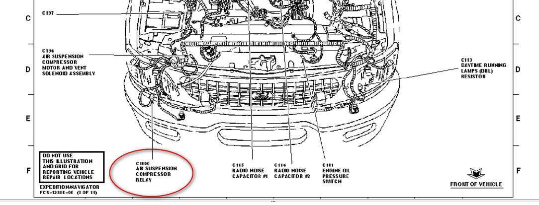
- Compressor Not Running: Check the compressor's power supply (using the wiring diagram to identify the correct wires) and ground connection. A blown fuse or a faulty relay (shown on the diagram) could also be the problem. Use a multimeter to test for voltage at the compressor.
- Error Codes: Use an OBD-II scanner to retrieve error codes. Consult the vehicle's service manual and the air suspension diagram to interpret the codes and identify the affected components.
- Uneven Ride Height: This could indicate a faulty ride height sensor or a problem with the solenoid valves that control the air flow to each air spring. The diagram helps you identify the correct components and their wiring.
Safety Considerations
Working on the air suspension system can be hazardous. Consider these points:
- High Pressure: The air suspension system operates at high pressures. Always depressurize the system before disconnecting any air lines. Failure to do so could result in serious injury. Follow the manufacturer's recommended depressurization procedure.
- Electrical Shock: Use caution when working with electrical components. Disconnect the battery before working on the system's wiring.
- Support the Vehicle: Never work under a vehicle that is only supported by a jack. Use jack stands to provide a safe and stable working platform.
- Eye Protection: Wear safety glasses to protect your eyes from debris and pressurized air.
- Component Integrity: Always inspect components for wear, cracks, or damage before reinstalling them. Replace damaged components with new ones.
Understanding the 2000 Ford Expedition air suspension diagram is essential for effective diagnosis and repair. By carefully studying the diagram and following safe working practices, you can confidently tackle many common air suspension problems.
We have the complete, high-resolution 2000 Ford Expedition air suspension diagram available for download. This detailed file will provide you with an invaluable resource for your repair or modification project. Click here to download the diagram.