
2000 Ford Taurus Serpentine Belt Diagram
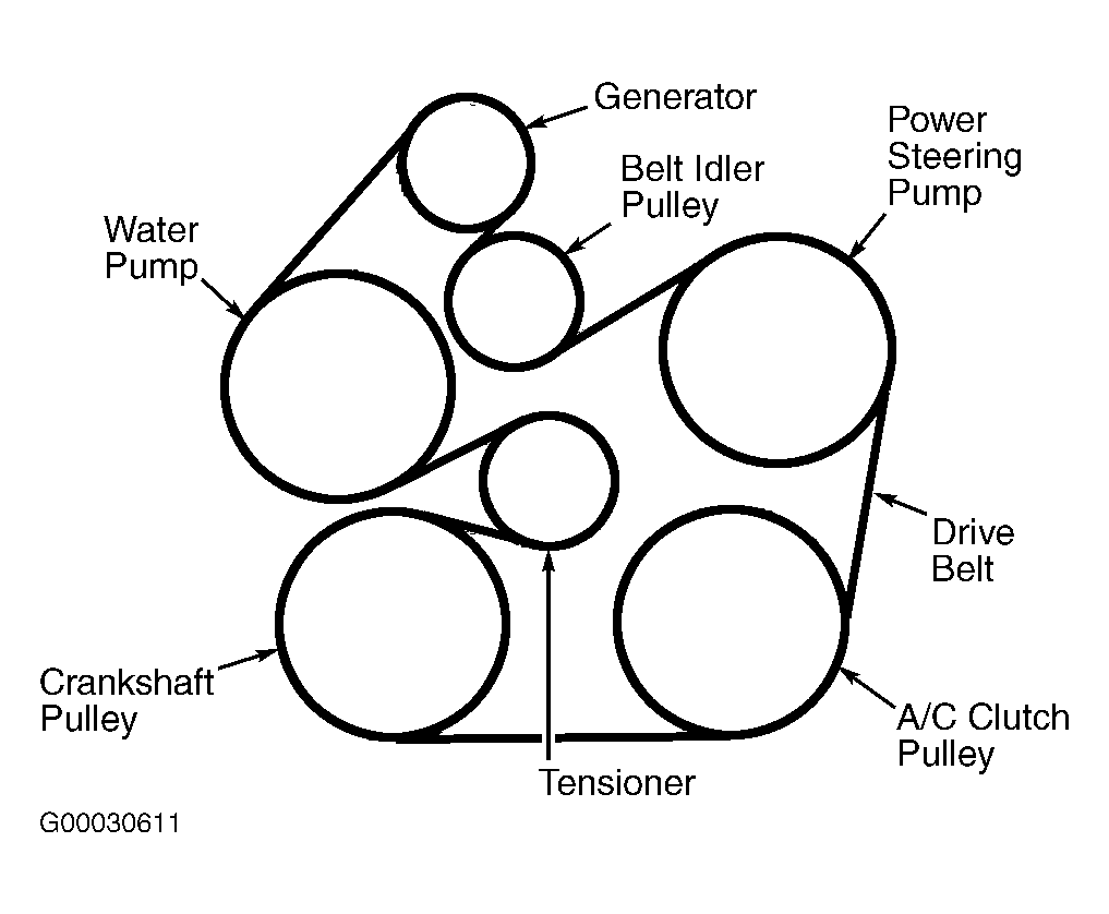
Alright, let's dive into the serpentine belt diagram for the 2000 Ford Taurus. Whether you're tackling a repair, performing routine maintenance, or simply want to understand how your engine accessories are driven, knowing this diagram is crucial. We're talking about keeping your power steering, alternator, air conditioning, and potentially your water pump all humming along smoothly.
Purpose of the Serpentine Belt Diagram
The serpentine belt diagram is essentially a roadmap. It visually depicts the routing of the serpentine belt around the various pulleys driven by your engine's crankshaft. Its primary purpose is to show the correct path for the belt. Without it, you're guessing – and guessing wrong can lead to component damage, belt failure, and a stranded vehicle. It’s invaluable for replacing a worn or broken belt, diagnosing squealing noises, and ensuring correct belt tension. It’s also great for understanding how the various components on the front of your engine are interconnected. Knowing the route the belt travels can even aid in diagnosing issues with individual components themselves.
Key Specs and Main Parts (2000 Ford Taurus)
For the 2000 Ford Taurus, you'll primarily encounter two engine options which will influence your exact serpentine belt routing:
* 3.0L OHV (Vulcan) V6: This is the more common engine. Its serpentine belt layout is relatively straightforward. * 3.0L DOHC (Duratec) V6: This engine, while also a 3.0L, has a different head design (Dual Overhead Camshaft) and subsequently, a slightly different belt routing. Pay close attention to which engine you have.Key components shown on the diagram, and driven by the serpentine belt, include:
* Crankshaft Pulley (Damper): This is the driving force. Connected directly to the crankshaft, it provides the rotational power to the belt. * Alternator Pulley: Driven by the belt, the alternator generates electricity to power your car's electrical system and charge the battery. * Power Steering Pump Pulley: Powers the hydraulic assistance for your steering system. * Air Conditioning Compressor Pulley: Engages to drive the A/C compressor, providing cool air. * Water Pump Pulley: Circulates coolant throughout the engine to maintain operating temperature. *Note: On some Taurus models, the water pump may be driven by the timing chain inside the engine and not the serpentine belt.* Always check your specific diagram. * Idler Pulley(s): Smooth, non-driven pulleys that guide the belt around the various components, maintaining optimal wrap angle and preventing slippage. * Tensioner Pulley: This is a spring-loaded pulley that applies constant tension to the serpentine belt, preventing it from slipping or becoming loose. Maintaining proper tension is crucial for belt longevity and proper component operation. A failing tensioner is a very common cause of serpentine belt noise.Symbols and Diagram Conventions
Understanding the symbols on the diagram is essential for interpreting it correctly. Here’s a breakdown:
* Solid Lines: Represent the serpentine belt itself. The thickness may vary, but generally, a thicker line indicates the main belt path. * Pulleys: Represented by circles, often with a small "X" or some internal detail to differentiate them. * Arrows: Indicate the direction of rotation for each pulley. This is important for understanding how the belt is routed and whether a pulley is driven directly or indirectly. * Component Labels: Each pulley will be labeled with an abbreviation or full name (e.g., "ALT" for Alternator, "P/S" for Power Steering, "A/C" for Air Conditioning, "CRK" for Crankshaft, "IDL" for Idler, "TEN" for Tensioner, "W/P" for Water Pump). * Belt Routing: The diagram will clearly show how the belt wraps around each pulley. Look for specific routing directions, especially around the tensioner and idler pulleys. * Engine Type Specificity: Diagrams might feature notes or separate sections highlighting variations based on the engine type (Vulcan vs. Duratec).Color coding, while not always present, can further enhance clarity. If present, colors might distinguish between the belt's front and back surfaces or highlight specific sections of the routing path.
How It Works: Power Transmission
The serpentine belt system is a clever design for efficiently transferring power from the engine's crankshaft to multiple accessories. The crankshaft pulley is connected directly to the engine's rotating crankshaft. As the crankshaft spins, it turns the crankshaft pulley, which, in turn, drives the serpentine belt. The belt then wraps around the other pulleys, transferring the rotational force to the alternator, power steering pump, air conditioning compressor, and (potentially) the water pump. The tensioner pulley ensures the belt remains tight against all the pulleys, preventing slippage and maintaining optimal power transfer. Without proper tension, the belt will slip, components won't operate efficiently, and the belt will likely wear out prematurely.
Real-World Use and Troubleshooting
Let's say you're experiencing a persistent squealing noise from the front of your engine. Here's how the serpentine belt diagram can help:
1. Visual Inspection: Use the diagram to visually inspect the belt's routing. Is it correctly positioned on all the pulleys? Is it damaged, cracked, or frayed? 2. Tension Check: Refer to the diagram to locate the tensioner pulley. Check if the tensioner arm moves freely and provides adequate tension. A weak or seized tensioner is a common culprit for squealing. 3. Pulley Condition: With the engine off, use the diagram to identify each pulley. Manually spin each pulley. Do you feel any roughness, hear any grinding noises, or notice any wobble? These are signs of a failing bearing within the pulley. 4. Component Function: While the engine is running (with caution!), use the diagram to understand which components the belt drives. If, for instance, the A/C isn't working, check if the compressor pulley is engaging properly when the A/C is turned on. 5. Belt Replacement: When replacing the belt, the diagram is your lifeline. Carefully note the routing before removing the old belt. Once the old belt is off, use the diagram to ensure the new belt is routed correctly around all pulleys before releasing the tensioner.Safety Precautions
Working on the serpentine belt system can be hazardous if proper precautions aren't taken:
* Disconnect the Negative Battery Terminal: This prevents accidental starting of the engine while your hands are near moving parts. * Hot Engine: Avoid working on the engine immediately after it's been running. Allow it to cool down to prevent burns. * Moving Parts: Never place your hands or tools near the serpentine belt or pulleys while the engine is running. These components rotate at high speeds and can cause serious injury. * Protective Gear: Wear safety glasses to protect your eyes from debris and gloves to protect your hands from sharp edges. * Belt Tensioner: The belt tensioner is spring-loaded and can snap back forcefully when released. Use the correct tool (usually a serpentine belt tool) to safely relieve the tension.By understanding your 2000 Ford Taurus serpentine belt diagram and following these safety guidelines, you can confidently tackle a wide range of maintenance and repair tasks.
We have the complete serpentine belt diagram file for both the Vulcan and Duratec engines available for download. This will provide you with a high-resolution image for easy reference during your project. Please feel free to download it.