2000 Gmc Sierra Radio Wiring Diagram
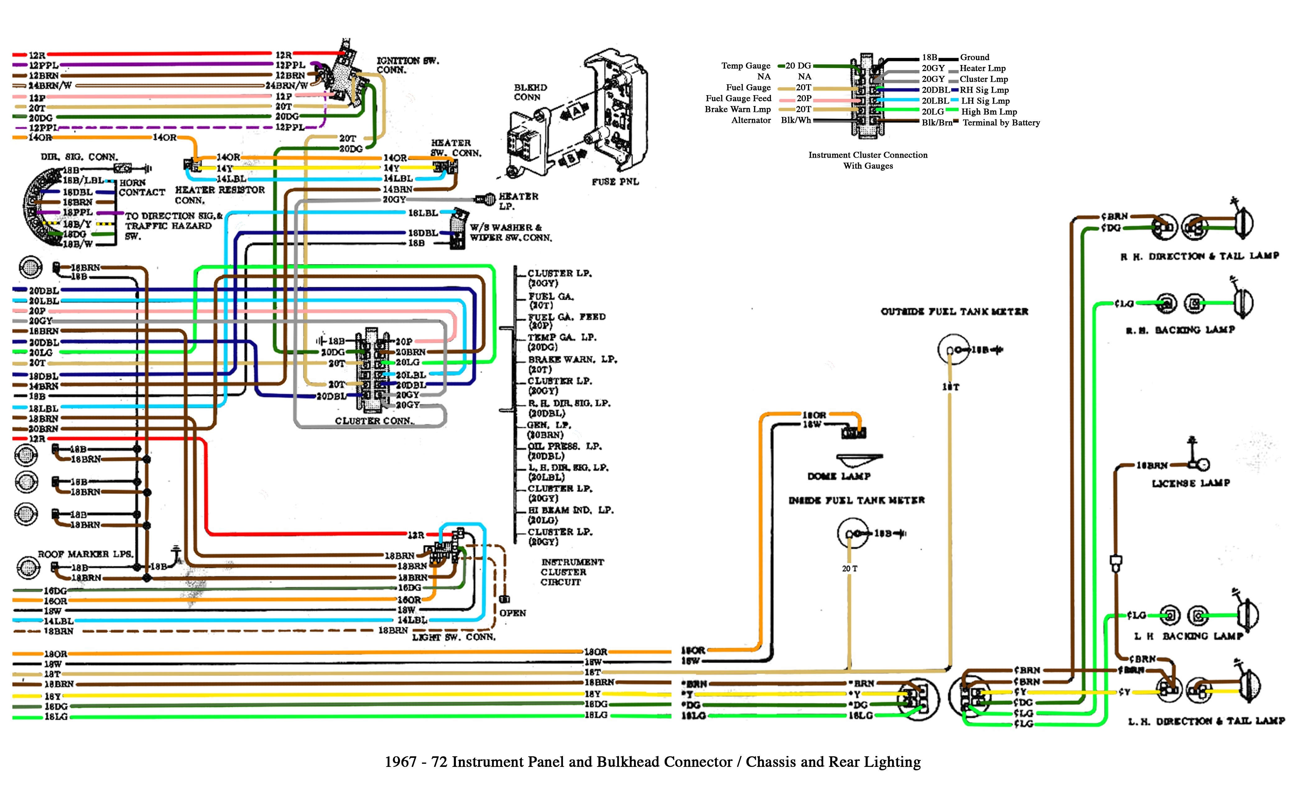
Understanding the 2000 GMC Sierra radio wiring diagram is crucial for anyone undertaking audio system modifications, repairs, or even just diagnosing electrical problems within your truck. This isn't just about swapping out a head unit; it's about understanding the complex interplay of power, ground, speakers, and data signals that make up your vehicle's entertainment system. Knowing this wiring landscape empowers you to make informed decisions, avoid costly mistakes, and potentially save a bundle on professional repairs.
Purpose of the Wiring Diagram
The wiring diagram is essentially a roadmap of your radio's electrical system. It serves several important purposes:
- Troubleshooting: Quickly identify faulty wires, shorts, or open circuits preventing your radio from working correctly.
- Upgrading: Safely install aftermarket head units, amplifiers, speakers, or subwoofers. Knowing which wire does what prevents damage to your factory system or the new components.
- Repairing: Correctly splice or reconnect damaged wires due to accidents, corrosion, or rodent damage.
- Learning: Gaining a deeper understanding of automotive electrical systems and how they function. This knowledge can be applied to other areas of your vehicle.
- Customization: Integrating additional features like backup cameras, steering wheel control interfaces, or Bluetooth modules.
Key Specs and Main Parts of the 2000 GMC Sierra Radio Wiring
The 2000 GMC Sierra radio wiring is a 12-volt DC system. This is important because you *must* use components that are rated for this voltage. Using higher voltage components is fine, but never use anything rated for lower voltage. The wiring diagram typically includes the following components:
- Head Unit: The main control unit for the audio system (receiver, CD player, etc.).
- Speakers: Front left, front right, rear left, rear right. Some models may have tweeters and subwoofers.
- Antenna: Receives radio signals.
- Wiring Harness: A collection of wires bundled together that connect the radio to the vehicle's electrical system. This is usually a standardized connector, but modifications may have been made by previous owners.
- Ground (Chassis Ground): A wire that connects to the vehicle's metal frame, providing a common reference point for electrical circuits. Essential for proper circuit function.
- Power Wire (Battery +12V): Supplies constant power to the radio, allowing it to retain memory (station presets, clock settings, etc.). Often fused for safety.
- Switched Power Wire (Ignition +12V): Supplies power to the radio when the ignition is turned on.
- Illumination Wire: Dims the radio display when the headlights are turned on.
- Data Wires (if applicable): Used for communication between the radio and other vehicle systems, such as the BCM (Body Control Module). This is important for features like steering wheel controls and theft deterrent systems. These are often part of a serial data bus like GM's class II data system.
- Factory Amplifier (if equipped): Some Sierras came with a separate amplifier that powers the speakers. The wiring diagram will show the connections between the head unit and the amplifier, as well as the amplifier and the speakers.
Understanding the Symbols
Wiring diagrams utilize a standardized set of symbols to represent electrical components and connections. Understanding these symbols is crucial for interpreting the diagram correctly.
- Solid Lines: Represent wires. The thickness of the line may sometimes indicate the wire gauge (thicker lines = larger gauge wires, capable of carrying more current).
- Dashed Lines: Often represent shielded cables or data connections.
- Circles: Can represent connectors, splices, or other connection points. Sometimes they represent inline fuses.
- Squares/Rectangles: Typically represent components like relays, switches, or the head unit itself.
- Ground Symbol: Usually a series of horizontal lines decreasing in length, indicating a connection to the vehicle's chassis ground.
- Battery Symbol: Represents the vehicle's battery, showing the positive (+) and negative (-) terminals.
- Fuse Symbol: Looks like a squiggly line inside a rectangle, indicating a fuse.
- Speaker Symbol: Resembles a loudspeaker.
Color Codes: Wires are often color-coded to help identify their function. The wiring diagram will have a key that lists the color codes and their corresponding functions. Common colors include:
- Red: Typically represents constant power (+12V Battery).
- Yellow: Usually represents switched power (+12V Ignition).
- Black: Almost always represents ground.
- Blue: Often used for antenna power or amplifier turn-on.
- White/Gray: Commonly used for speaker wires.
- Other colors: Various colors are used for signal wires, illumination, and other functions. Always refer to the diagram's color code key.
How It Works: A Simplified Explanation
The basic principle is simple: the radio receives power from the battery and ignition, processes audio signals from various sources (antenna, CD player, etc.), amplifies those signals, and sends them to the speakers. The speakers convert the electrical signals into sound waves that you hear.
The constant power wire keeps the radio's memory alive, while the switched power wire activates the radio when the ignition is turned on. The ground wire provides a return path for the electrical current, completing the circuit. Speaker wires carry the amplified audio signals to the speakers. Data wires (if present) allow the radio to communicate with other vehicle systems.
Real-World Use: Basic Troubleshooting
Here are some basic troubleshooting tips using the wiring diagram:
- Radio Won't Turn On: Use a multimeter to check for voltage on the constant power wire and the switched power wire. Also, verify that the ground connection is good. Check the fuses associated with the radio circuit. A blown fuse is often the culprit.
- No Sound: Check the speaker connections and the speaker wires for damage. Use a multimeter to test the speaker wires for continuity (a complete circuit). If you have a factory amplifier, check its power and ground connections.
- Dim Display: Check the illumination wire connection.
- Static or Distortion: Check the antenna connection. Look for loose or corroded connections in the speaker wiring.
Important: Before doing any electrical work, always disconnect the negative terminal of the battery. This prevents accidental shorts and damage to your vehicle's electrical system.
Safety Considerations
Working with automotive electrical systems can be dangerous. Be aware of the following:
- Airbag System: Be extremely careful when working near the airbag system. Accidental deployment can cause serious injury. If you are not comfortable working around airbags, consult a professional. Refer to the vehicle's service manual for airbag deactivation procedures.
- Short Circuits: Short circuits can cause fires and damage to electrical components. Always use proper wiring techniques and ensure that all connections are secure and insulated.
- Voltage: While 12V DC is relatively low voltage, it can still deliver a significant electrical shock. Avoid touching exposed wires or terminals.
- Component Damage: Incorrect wiring can damage the radio, speakers, or other electrical components. Double-check your work before applying power.
- Tools: Use the appropriate tools for the job. Crimping tools, wire strippers, and multimeters are essential for safe and effective electrical work.
- Consult a Professional: If you are unsure about any aspect of the wiring, consult a qualified automotive electrician.
The 2000 GMC Sierra radio wiring diagram is your indispensable guide to navigating the audio system's electrical landscape. By understanding its symbols, components, and principles, you can confidently tackle repairs, upgrades, and customizations while minimizing the risk of costly errors. With patience, attention to detail, and adherence to safety precautions, you can unlock the full potential of your vehicle's audio system. This empowers you to confidently troubleshoot, upgrade, and maintain your system.
To get started, download the full 2000 GMC Sierra Radio Wiring Diagram now. Having the full diagram at your fingertips will make any audio-related project much easier and safer.