2000 Jeep Grand Cherokee Laredo Fuse Box Diagram
Welcome, fellow gearheads! Today, we're diving deep into the electrical heart of the 2000 Jeep Grand Cherokee Laredo: its fuse box. Understanding this often-overlooked component is crucial for diagnosing electrical problems, performing modifications, and generally keeping your ZJ running smoothly. Forget blindly swapping parts; with a proper understanding of the fuse box diagram, you'll be able to pinpoint issues with surgical precision.
Why Bother with the Fuse Box Diagram?
So, why should you, an experienced DIYer, bother learning about this seemingly mundane piece of your Jeep? The answer is simple: the fuse box is the central nervous system of your vehicle's electrical system. Knowing its layout is vital for:
- Troubleshooting Electrical Issues: Identifying and replacing blown fuses is the first step in diagnosing many electrical problems, from malfunctioning lights to a dead radio.
- Performing Modifications: When adding aftermarket accessories like lights, radios, or amplifiers, you'll need to tap into the fuse box for power. Understanding the diagram ensures you choose the right circuits and protect your system.
- Preventative Maintenance: Regularly inspecting the fuse box for corrosion or loose connections can prevent future electrical problems.
- Learning Your Vehicle: Familiarizing yourself with the fuse box is part of understanding how your vehicle works. It empowers you to perform your own repairs and maintenance, saving time and money.
Key Specs and Main Parts
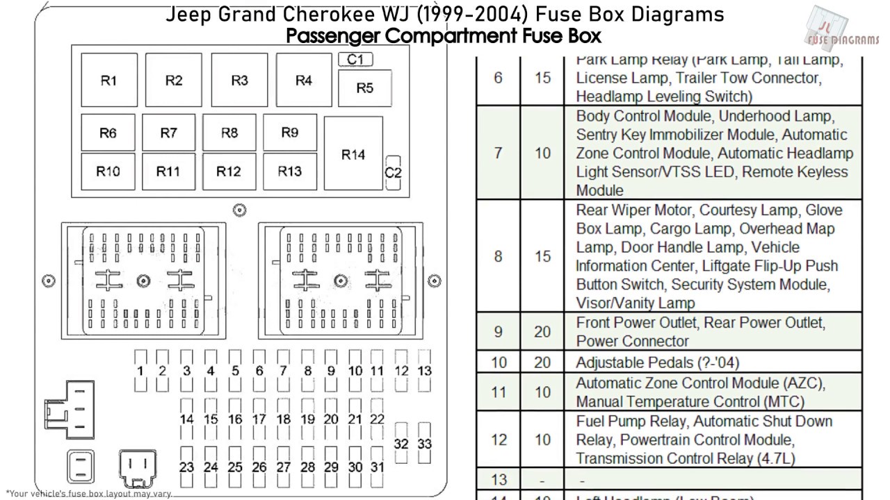
The 2000 Jeep Grand Cherokee Laredo, like most vehicles, actually has multiple fuse boxes. We'll focus on the two most important ones:
- The Junction Block (Interior Fuse Box): Located typically under the dashboard, usually on the driver's side, behind a removable panel. This houses fuses and relays for interior components like lights, radio, power windows, and the instrument panel.
- The Power Distribution Center (Under-Hood Fuse Box): Located in the engine compartment, this contains fuses and relays for essential vehicle systems like the engine control unit (ECU), fuel pump, headlights, and starting system. This is often a larger, more robust box.
The diagram typically specifies the fuse location, the amperage rating of the fuse, and the circuit it protects. Common amperage ratings you'll find include 5A, 10A, 15A, 20A, 25A, 30A, and higher for certain circuits. Fuses are designed to be the weakest link in a circuit, intentionally blowing to protect more expensive components from damage caused by overcurrent.
Relays are electromechanical switches that allow a low-current circuit to control a high-current circuit. They are used to control components that require a lot of power, such as headlights, starters, and air conditioning compressors. The fuse box also contains various connectors and terminals that provide electrical connections to the vehicle's wiring harness.
Decoding the Symbols: A Guide to Understanding the Diagram
A fuse box diagram is essentially a map of the electrical circuits protected by each fuse. Understanding the symbols is key to interpreting the diagram correctly.
- Lines: Lines represent wires connecting the fuse to the protected component. Thicker lines might indicate larger gauge wires designed for higher current.
- Colors: Wire colors are often indicated in the diagram, though this can vary depending on the specific diagram and printer. Knowing the wire color can be immensely helpful when tracing wires in the vehicle. Common colors include red (power), black (ground), and various other colors for specific circuits.
- Fuse Symbol: The fuse symbol is typically a zig-zag line within a rectangle or a simple straight line. The number next to the symbol indicates the fuse's amperage rating.
- Relay Symbol: The relay symbol usually consists of a coil and a switch. The coil represents the relay's electromagnet, and the switch represents the contacts that are opened or closed when the relay is activated.
- Component Symbols: Various symbols represent the components protected by the fuses, such as lights, motors, sensors, and modules. These symbols can vary, so it's helpful to consult a legend if provided with the diagram. For example, a headlight might be represented by a stylized bulb.
Some diagrams also use abbreviations to indicate the circuit or component protected by the fuse. For example, "ECM" might stand for Engine Control Module, "IGN" for Ignition, and "PWR WDO" for Power Windows.
How It All Works: The Fuse Box in Action
Imagine the fuse box as a power distribution center for your Jeep's electrical system. Power from the battery flows into the fuse box, and then is distributed to various circuits through individual fuses. Each fuse protects a specific circuit from overcurrent. If a circuit draws too much current (e.g., due to a short circuit or a faulty component), the fuse blows, breaking the circuit and preventing damage to the wiring and components.
When a fuse blows, it's not just a random occurrence. It's a symptom of an underlying problem. Replacing the fuse without addressing the root cause will likely result in the new fuse blowing as well. Therefore, it's essential to diagnose the cause of the blown fuse before replacing it.
Tracing a Circuit: Using the diagram, you can trace the circuit protected by a particular fuse. Start by identifying the fuse in the diagram. Then, follow the lines and symbols to see which components are connected to that fuse. This can help you narrow down the potential causes of a blown fuse or other electrical problem.
Real-World Use: Troubleshooting Tips
Here's a basic troubleshooting scenario using the fuse box diagram:
- Problem: Your headlights don't work.
- Step 1: Consult the fuse box diagram to locate the fuse for the headlights (likely labeled "Headlights" or "H/LP").
- Step 2: Visually inspect the fuse. A blown fuse will typically have a broken filament or a darkened appearance.
- Step 3: If the fuse is blown, replace it with a fuse of the same amperage rating. Never use a fuse with a higher amperage rating, as this could damage the wiring and components.
- Step 4: If the new fuse blows immediately, there is a short circuit or an overcurrent condition in the headlight circuit. Further diagnosis is needed to pinpoint the cause. This might involve checking the wiring, connectors, and headlight bulbs for damage.
Important Note: Always disconnect the negative battery cable before working on the electrical system to prevent accidental shorts and shocks.
Safety First: Identifying Risky Components
Working with electricity can be dangerous. Some circuits in the fuse box carry high voltage and amperage, which can cause serious injury or even death. Here are some key safety considerations:
- High-Current Circuits: Be especially careful when working with circuits that power the starter, alternator, and air conditioning compressor. These circuits can carry hundreds of amps.
- Airbag System: The airbag system has its own dedicated fuse and control module. Do not tamper with the airbag system unless you are a qualified technician. Accidental deployment of the airbags can cause serious injury.
- Fuel Pump Circuit: The fuel pump circuit carries flammable fuel. Be careful to avoid sparks or open flames when working on this circuit.
- Always Disconnect the Battery: Disconnecting the negative battery cable is the most important safety precaution. This will prevent accidental shorts and shocks.
Never bypass a fuse! This is extremely dangerous and can cause serious damage to your vehicle or even a fire.
Remember, if you're not comfortable working on the electrical system, it's always best to consult a qualified mechanic. Electrical problems can be complex, and improper repairs can be costly and dangerous.
We have the complete 2000 Jeep Grand Cherokee Laredo Fuse Box Diagram file available for download. This detailed diagram will be an invaluable resource for all your electrical troubleshooting and modification needs.