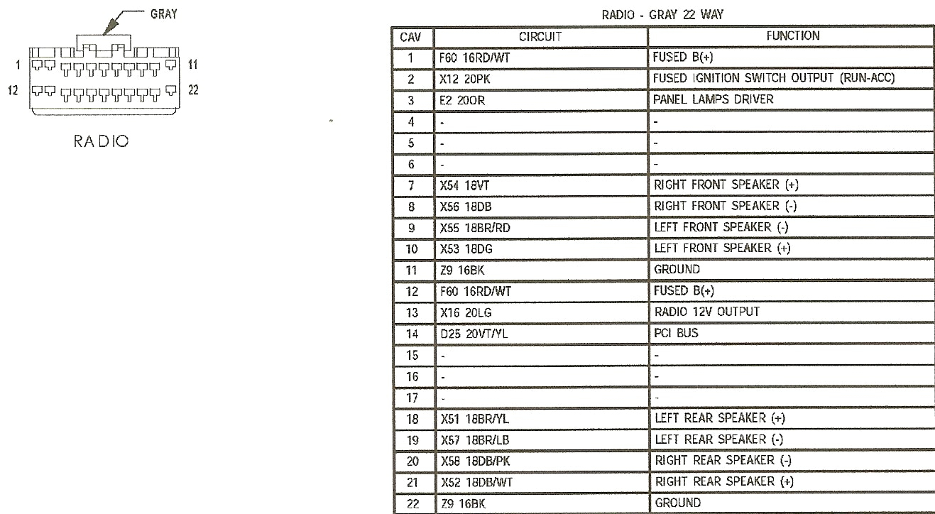
2000 Jeep Grand Cherokee Radio Wiring Diagram
Let's dive into the wiring diagram for the 2000 Jeep Grand Cherokee's radio. Understanding this diagram is invaluable whether you're troubleshooting audio issues, upgrading your stereo, or simply trying to decipher the spaghetti of wires behind your dash. It's the roadmap to your Jeep's audio system, and we're here to help you read it.
Purpose of the Radio Wiring Diagram
Why bother with a wiring diagram? There are several good reasons:
- Troubleshooting: If your radio isn't working correctly (no power, no sound, intermittent issues), the diagram helps you trace the circuit and identify potential problem spots like faulty wiring, blown fuses, or disconnected connectors.
- Upgrading: Planning to install a new head unit, amplifier, or speakers? The diagram shows you how the existing system is wired, making it easier to integrate aftermarket components. It avoids the pitfalls of haphazardly cutting and splicing wires.
- Repairing: Damaged wiring from rodent activity or accidental cuts can be repaired accurately using the diagram as a guide.
- Learning: Even if you don't have an immediate problem, studying the diagram can help you understand how your car's electrical system functions, making you a more confident and capable DIY mechanic.
Key Specs and Main Parts
Before we jump into the diagram itself, let's identify the key components of the 2000 Grand Cherokee radio system. The exact configuration may vary slightly depending on whether you have the standard or premium sound system, but the core elements remain the same.
- Head Unit (Radio): The central control unit, housing the tuner, CD player (if equipped), and user interface. This is where you control the volume, station selection, and other audio settings.
- Speakers: Located in the doors and possibly the rear cargo area, responsible for converting electrical signals into audible sound. The 2000 Grand Cherokee typically has four or six speakers depending on the trim level.
- Amplifier (Optional): Some models, particularly those with the premium sound system (like Infinity Gold), have a separate amplifier located under the rear seat or in the cargo area. This amplifies the signal from the head unit before it reaches the speakers, providing more power and better sound quality.
- Wiring Harnesses: Bundles of wires connecting the various components. Key harnesses include the main radio harness, speaker harnesses, and the amplifier harness (if applicable).
- Antenna: Receives radio signals.
- Fuses: Protective devices that prevent damage from electrical overloads. The radio circuit typically has its own fuse, located in the fuse box (usually under the hood or in the cabin).
For the 2000 Grand Cherokee, the factory radio typically uses a standard Chrysler/Mopar wiring harness. Aftermarket adapters are readily available to convert this harness to a standard ISO connector, simplifying the installation of aftermarket head units.
Understanding the Symbols on the Wiring Diagram
Wiring diagrams use standardized symbols and conventions to represent electrical components and connections. Here's a breakdown of what you'll typically find:
- Lines: Lines represent wires. Thicker lines may indicate wires carrying more current.
- Colors: Each wire is identified by a color code (e.g., RED, BLU, GRN, YEL). These codes are usually abbreviated. Following the color codes is crucial for identifying the correct wires.
- Circles/Dots: Where lines intersect, a solid dot usually indicates a physical connection. If lines cross without a dot, it means they are passing over each other without connecting.
- Rectangles: Often represent components like the head unit, amplifier, or other modules.
- Squares: Usually represent ground connections. These are typically connected to the chassis of the vehicle.
- Wave Symbol: Represents a speaker.
- Fuse Symbol: Looks like a zigzag line inside a rectangle. Indicates a fuse.
- Connectors: Represented by various shapes (often circles or rectangles with lines pointing inwards) and are usually labeled with a number or letter. These symbols illustrate where wiring harnesses connect and disconnect.
Crucially, pay close attention to the legend on the wiring diagram. The legend defines all the symbols and abbreviations used in that specific diagram. It's your key to accurate interpretation.
How It Works: A Simplified Overview
The radio system's basic operation is relatively straightforward:
- Power: The head unit receives power from the vehicle's electrical system via the ignition switch and a constant 12V source. The ignition switch power allows the radio to turn on and off with the key, while the constant 12V source maintains memory (e.g., radio presets).
- Signal Processing: The head unit receives radio signals via the antenna and processes them. It also handles audio from other sources like a CD player or auxiliary input.
- Amplification: The head unit amplifies the audio signal (or sends it to an external amplifier).
- Output: The amplified signal is sent to the speakers, which convert it into sound.
- Grounding: All components are properly grounded to the vehicle's chassis to complete the electrical circuit.
Real-World Use: Basic Troubleshooting Tips
Here are a few common problems and how the wiring diagram can help:
- No Power to Radio: Check the radio fuse first. If the fuse is blown, replace it. If it blows again immediately, there's a short circuit somewhere in the wiring. Use the wiring diagram to trace the power wire from the fuse box to the head unit, looking for any damaged insulation or pinched wires.
- No Sound from Speakers: Check the speaker wires for continuity (using a multimeter) from the head unit to the speakers. Make sure the speakers are properly connected. If you have a separate amplifier, verify that it's receiving power and is properly grounded.
- Intermittent Sound: This could be a loose connection or a faulty wire. Wiggle the wiring harnesses while the radio is playing to see if you can reproduce the problem. Use the wiring diagram to identify the specific wires involved.
- Distorted Sound: This could indicate a blown speaker or a problem with the amplifier (if equipped). Test the speakers with a known good audio source to rule out speaker damage.
Safety Precautions
Working with automotive electrical systems can be dangerous. Here are some essential safety tips:
- Disconnect the Battery: Before working on any electrical component, disconnect the negative (-) terminal of the battery. This prevents accidental shorts and potential electrical shocks.
- Use Proper Tools: Use insulated tools designed for automotive electrical work.
- Be Careful with Airbags: The airbag system is a potentially dangerous component. Avoid tampering with any wiring or components related to the airbag system unless you are specifically trained to do so. Accidental deployment can cause serious injury.
- Protect Your Eyes: Wear safety glasses to protect your eyes from flying debris or accidental sparks.
- Don't Work Alone: It's always a good idea to have someone nearby when working on your car, in case of an emergency.
Important: The radio and amplifier circuits can carry significant current. Short circuits can quickly overheat wires and cause fires. Always use the correct fuse rating for the circuit. Never replace a blown fuse with a higher amperage fuse.
By understanding the wiring diagram and following safe practices, you can confidently tackle a variety of radio-related repairs and upgrades on your 2000 Jeep Grand Cherokee. Remember to always double-check your work and consult the wiring diagram for clarification when needed.
We have the full 2000 Jeep Grand Cherokee radio wiring diagram available. You can download it to have a comprehensive reference guide for your projects and troubleshooting needs.