
2000 Nissan Frontier Fuse Box Diagram
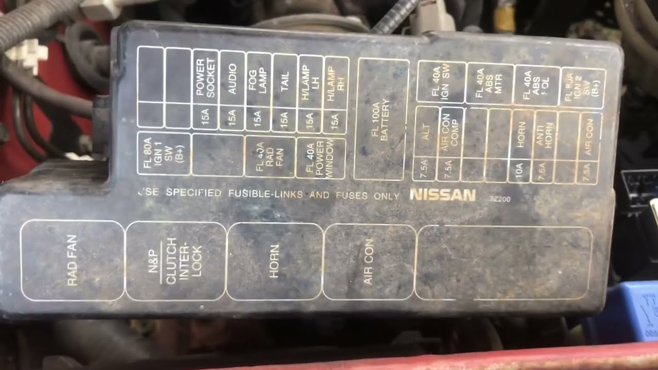
Let's dive into the intricate world of the 2000 Nissan Frontier's fuse box diagram. Whether you're tackling electrical gremlins, planning modifications, or simply expanding your automotive knowledge, understanding this diagram is crucial. Think of it as a roadmap to your Frontier's electrical system, enabling you to diagnose and repair issues effectively and safely.
Why Bother with the Fuse Box Diagram?
The fuse box diagram is your go-to reference for a range of tasks, including:
- Troubleshooting Electrical Problems: Identifying blown fuses is the first step in resolving many electrical issues. The diagram tells you which fuse protects which circuit.
- Performing Electrical Repairs: Knowing which fuse controls a specific component (e.g., headlights, radio, power windows) is essential when troubleshooting or repairing that component.
- Installing Aftermarket Accessories: Properly tapping into the electrical system for accessories like auxiliary lights or a new stereo requires understanding the circuit layout. The diagram helps you identify suitable circuits and ensure proper fuse protection.
- General Understanding of the Vehicle's Electrical System: Even if you're not actively working on your Frontier, studying the fuse box diagram offers valuable insights into how its electrical components are organized and protected.
Key Specs and Main Parts of the 2000 Frontier Fuse System
The 2000 Nissan Frontier typically has two main fuse boxes:
- Interior Fuse Box: Located inside the cabin, usually under the dashboard on the driver's side. This fuse box primarily protects circuits related to interior components like lights, radio, power windows, and the cigarette lighter (accessory power).
- Engine Compartment Fuse Box: Situated in the engine bay, this fuse box houses fuses and relays for critical engine management and safety systems, such as the fuel pump, ignition system, headlights, ABS, and cooling fan.
Within each fuse box, you'll find several key components:
- Fuses: These are sacrificial devices designed to protect circuits from overcurrent. They contain a thin wire that melts and breaks the circuit if the current exceeds a safe level. Fuses are rated in amperes (amps), indicating the maximum current they can handle.
- Relays: These are electromechanical switches that control high-current circuits using a low-current signal. They're commonly used for headlights, the starter motor, and other power-hungry components. They allow a small switch (like a headlight switch) to control a much larger load.
- Fuse Puller: Usually located within one of the fuse boxes, this small plastic tool helps you remove fuses without damaging them.
- Diagram Label: This is typically a sticker or card attached to the fuse box cover that identifies each fuse and relay, often including its amperage rating and the circuit it protects.
Decoding the Symbols, Lines, and Colors
Fuse box diagrams use a combination of symbols, lines, and colors to convey information. Here's a breakdown:
- Fuses: Fuses are generally represented by a rectangular or square symbol. Some diagrams may include the amperage rating directly on the symbol (e.g., "10A," "15A").
- Relays: Relays are often depicted as a square or rectangle with a coil symbol inside, indicating the electromagnet. The diagram may also show the relay's pin configuration.
- Lines: Lines represent the electrical circuits. A solid line indicates a direct connection, while a dashed line might indicate a connection through a switch or other component.
- Colors: Colors are used to differentiate between circuits, although their standardization can vary. Common color codes include:
- Red: Often indicates a direct battery connection (unswitched power).
- Yellow: May represent a circuit powered by the ignition switch.
- Blue: Can signify a circuit related to lighting.
Note: Always refer to the specific diagram for your 2000 Frontier as color codes can vary.
- Icons: Many diagrams use icons to represent the components protected by each fuse. Common icons include headlights, a radio, a window, a cigarette lighter, and an engine symbol.
How the Fuse System Works
The fuse system acts as a safeguard for your Frontier's electrical components. When a fault occurs in a circuit – for example, a short circuit caused by damaged wiring – the current flow increases dramatically. This excessive current generates heat in the fuse wire, causing it to melt and break the circuit. By interrupting the current flow, the fuse prevents damage to the wiring, components, and potentially even a fire.
Relays function as remote-controlled switches. A small current is applied to the relay's coil, which creates an electromagnetic field that pulls a switch closed, completing a separate, high-current circuit. This allows a low-current signal from a dashboard switch to control a high-current device like the headlights.
Real-World Use: Basic Troubleshooting
Here's a basic troubleshooting scenario:
- Symptom: Your headlights aren't working.
- Check the Bulbs: First, rule out simple causes. Ensure the headlight bulbs themselves are not burned out.
- Consult the Diagram: Locate the fuse box diagram (typically on the fuse box cover or in the owner's manual).
- Identify the Fuse: Identify the fuse labeled for the headlights.
- Inspect the Fuse: Use the fuse puller to remove the fuse and inspect it. A blown fuse will have a broken filament inside.
- Replace the Fuse: Replace the blown fuse with a new fuse of the same amperage rating. Never use a fuse with a higher amperage rating, as this could damage the wiring and components.
- Test: Turn on the headlights. If they work, you've solved the problem. If the fuse blows again immediately, there's likely a short circuit in the headlight wiring or the headlights themselves. This requires further investigation.
Safety First: Handling Risky Components
Working with electrical systems can be dangerous. Here are some crucial safety precautions:
- Disconnect the Battery: Before working on any electrical components, disconnect the negative (-) terminal of the battery. This prevents accidental shorts and electrical shocks.
- Use Proper Tools: Use insulated tools designed for automotive electrical work.
- Never Bypass Fuses: Never bypass a fuse with a wire or metal object. This eliminates the circuit protection and can lead to serious damage or a fire.
- Replace with the Correct Amperage: Always replace a blown fuse with a fuse of the same amperage rating. Using a higher amperage fuse can overload the circuit and cause a fire.
- Be Careful Around the Airbag System: Some fuses and circuits are related to the airbag system. Incorrect handling of these circuits can accidentally deploy the airbags, causing serious injury. Consult a qualified technician if you suspect issues with the airbag system. This is especially crucial as a 2000 Frontier may have aging components, increasing the risk of accidental deployment.
- When in doubt, consult a professional: If you are not comfortable working on electrical systems, seek help from a qualified mechanic.
Remember to always prioritize safety when working on your vehicle's electrical system.
We have a complete, downloadable PDF file of the 2000 Nissan Frontier Fuse Box Diagram ready for you. This diagram offers a detailed visual guide to both the interior and engine compartment fuse boxes, complete with fuse locations, amperage ratings, and circuit descriptions. Download it, print it out, and keep it handy in your garage for quick reference during your next DIY project or troubleshooting session.