2000 Nissan Maxima Fuse Box Diagram
Alright, let's dive into the 2000 Nissan Maxima's fuse box diagram. Whether you're tackling an electrical gremlin, adding aftermarket accessories, or just trying to understand your car better, knowing your way around the fuse box is crucial. This guide will break down everything you need to know, from the diagram's purpose to practical troubleshooting tips.
Why This Diagram Matters
The fuse box diagram is essentially your car's electrical system roadmap. It serves several key purposes:
- Repairing Electrical Issues: When a component stops working (e.g., a headlight, the radio, the power windows), the first thing to check is the corresponding fuse. The diagram tells you exactly which fuse to inspect.
- Installing Aftermarket Accessories: Adding things like a new stereo, aftermarket lights, or a dashcam often requires tapping into the car's electrical system. The diagram helps you identify suitable circuits to tap into safely.
- Understanding Your Car: Familiarizing yourself with the fuse box diagram gives you a better understanding of how your car's electrical system is laid out. This knowledge can be invaluable for preventative maintenance and diagnosing future problems.
- Preventing Further Damage: Replacing a blown fuse with the correct amperage fuse can prevent further damage to the circuit. Using a higher amperage fuse than specified can cause a fire.
Key Specs and Main Parts
The 2000 Nissan Maxima actually has *two* primary fuse boxes. Understanding their location and general function is essential:
Interior Fuse Box
This fuse box is typically located inside the car, often under the dashboard on the driver's side. It generally houses fuses for interior components like:
- Instrument cluster
- Radio/Stereo
- Power windows
- Power locks
- Cigarette lighter/Accessory power
- Interior lights
- Wiper and washer systems
Engine Compartment Fuse Box
This fuse box is located in the engine compartment, usually near the battery. It protects vital engine and drivetrain components, including:
- Engine Control Unit (ECU) – the car's brain
- Fuel pump
- Ignition system
- Cooling fan
- Headlights
- Anti-lock Braking System (ABS)
Key Specs: The amperage ratings of the fuses are critical. These are usually printed on the fuse itself (e.g., 10A, 15A, 20A). Using a fuse with a higher amperage than specified can overload the circuit and cause damage or fire. The diagram will explicitly state the correct amperage for each fuse location.
Decoding the Symbols, Lines, and Colors
Fuse box diagrams use a standardized set of symbols and conventions. Here’s a breakdown:
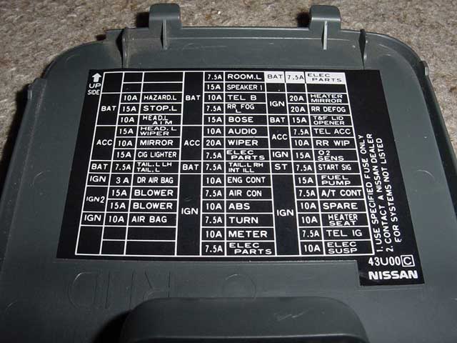
- Fuse Number: Each fuse location is typically assigned a number, making it easy to cross-reference with the diagram.
- Circuit Description: The diagram will include a brief description of what each fuse protects (e.g., "Headlight - Right," "Radio," "ECU").
- Amperage Rating: As mentioned, the amperage rating (e.g., 10A, 15A) is crucial. This indicates the maximum current the fuse can handle before it blows.
- Lines and Connections: Lines indicate the electrical connections between the fuse and the component it protects. Thicker lines might indicate heavier gauge wiring.
- Colors (in some diagrams): Some diagrams use color-coding to differentiate between different types of circuits (e.g., power, ground, signal). However, color-coding is not always consistent across all diagrams.
- Icons: Icons may represent the component being protected. For instance, a light bulb icon represents a headlight circuit, and a speaker icon means the radio circuit.
It is important to note that the specific format of the diagram might vary slightly depending on the source (e.g., the owner's manual, a repair manual, or an online database). However, the fundamental information (fuse number, circuit description, amperage rating) will always be present.
How It Works: A Simplified Explanation
The principle is pretty simple: a fuse is a safety device designed to protect an electrical circuit from overcurrent. It contains a thin wire that melts and breaks the circuit if the current exceeds the fuse's amperage rating. This "blowing" of the fuse prevents damage to the wiring and components connected to that circuit. Think of it as a sacrificial link. Without the fuse, a short circuit (a low-resistance path) could cause excessive current flow, leading to overheating, melting wires, and potentially a fire.
When a fuse blows, it's usually a sign of an underlying problem. Simply replacing the fuse without addressing the root cause is likely to result in the new fuse blowing as well. It's crucial to diagnose and fix the underlying issue *before* replacing the fuse.
Real-World Use: Basic Troubleshooting Tips
Here's a basic troubleshooting process when dealing with a blown fuse:
- Identify the Affected Component: What's not working? (e.g., headlight, radio, power window).
- Consult the Fuse Box Diagram: Locate the fuse associated with the non-functioning component.
- Inspect the Fuse: Visually inspect the fuse. A blown fuse will typically have a broken filament inside. You can also use a multimeter to test continuity across the fuse. If there's no continuity, the fuse is blown.
- Replace the Fuse: Replace the blown fuse with a new fuse of the *exact same amperage rating*.
- Test the Component: Does the component now work? If yes, you've likely solved the problem. However, if the new fuse blows immediately or shortly after, you have a more serious underlying problem.
- Investigate the Underlying Problem: If the fuse keeps blowing, you'll need to investigate the circuit for shorts, damaged wiring, or faulty components. This might involve using a multimeter to check for shorts to ground or resistance values. Consult a repair manual or seek professional help if you're not comfortable with this.
Safety First: Highlighting Risky Components
Working with electrical systems always involves some risk. Here are a few critical safety considerations:
- Disconnect the Battery: Before working on the fuse box, especially when dealing with the engine compartment fuse box, disconnect the negative terminal of the battery. This will help prevent accidental shorts and electrical shocks.
- Never Use a Higher Amperage Fuse: As emphasized before, using a fuse with a higher amperage rating than specified is extremely dangerous. It can overload the circuit, causing damage or a fire.
- Be Careful with Wiring: When inspecting wiring, be careful not to damage the insulation. Use insulated tools and avoid pulling or tugging on wires excessively.
- ECU Fuses: Fuses related to the Engine Control Unit (ECU) are particularly sensitive. Tampering with these circuits can damage the ECU, which can be costly to repair. If you suspect a problem with the ECU fuse, it's best to consult a qualified mechanic.
Disclaimer: Working on your car's electrical system can be dangerous. This information is for educational purposes only, and I am not responsible for any damage or injury that may result from your use of this information. If you're not comfortable working on your car's electrical system, seek professional assistance.
Remember to always consult your car's owner's manual for the most accurate and up-to-date information on your specific vehicle. With this guide and the proper safety precautions, you should be well-equipped to tackle most common fuse-related issues on your 2000 Nissan Maxima.
We have the 2000 Nissan Maxima fuse box diagram file available. You can download it to have a quick access when you're working on your car.