
2000 Toyota Camry Exhaust System Diagram
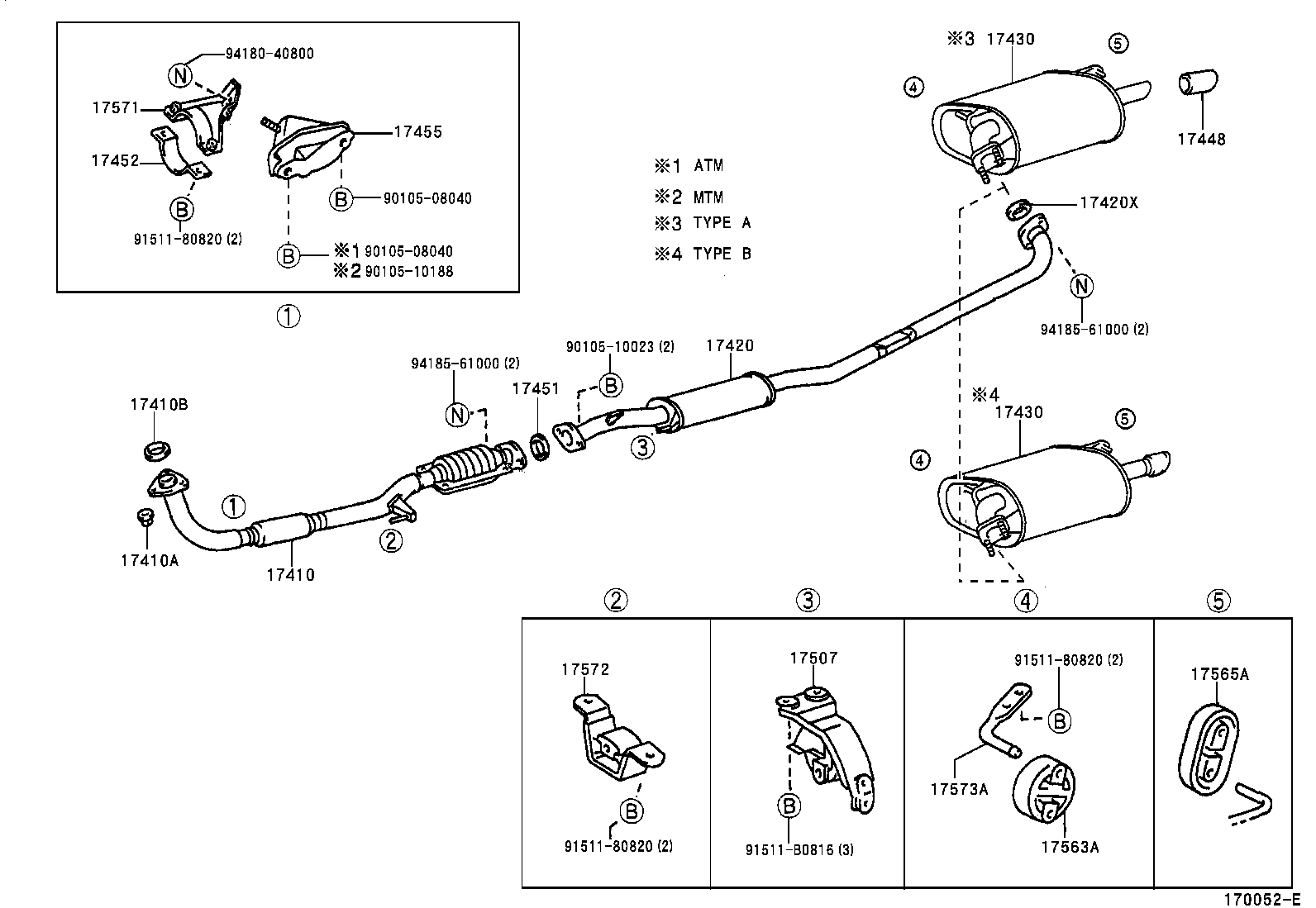
Welcome, fellow gearheads! Today, we're diving deep into the exhaust system of a 2000 Toyota Camry. Understanding this system is crucial for everything from basic maintenance and troubleshooting to performance upgrades and modifications. This article will provide a comprehensive breakdown of the 2000 Camry's exhaust system diagram, enabling you to confidently diagnose issues and tackle repairs. We even have the full diagram available for download.
Why Understanding the Diagram Matters
An exhaust system diagram is essentially a roadmap for your car's exhaust. It's a detailed visual representation of all the components involved in routing exhaust gases away from the engine. Having a grasp of this diagram is beneficial in several ways:
- Diagnosis: Pinpointing the source of a leak or a faulty component becomes much easier when you understand the layout. Is that rattling noise coming from the heat shield or a broken hanger? The diagram helps you trace the source.
- Repair and Replacement: Knowing the specific components and their arrangement allows you to order the correct parts and perform replacements efficiently. No more guesswork!
- Modifications and Upgrades: If you're planning on installing a performance exhaust system, headers, or even just a new muffler, the diagram is essential for understanding how the modifications will affect the overall system.
- Learning: Even if you're not planning on doing any immediate work, studying the diagram can simply deepen your understanding of how your car works.
Key Specs and Main Parts of the 2000 Camry Exhaust
The 2000 Toyota Camry came with several engine options, most commonly a 2.2L inline-4 (5S-FE) or a 3.0L V6 (1MZ-FE). While the fundamental principles of the exhaust system remain the same, the specific routing and components will vary slightly depending on the engine. Generally, the system consists of the following:
Main Components
- Exhaust Manifold: Bolted directly to the engine cylinder head, the exhaust manifold collects exhaust gases from each cylinder and directs them into a single pipe (or two pipes for the V6). The manifold is typically made of cast iron or, in some cases, stainless steel.
- Catalytic Converter: This is a crucial component for emissions control. The catalytic converter uses chemical reactions to reduce harmful pollutants like hydrocarbons (HC), carbon monoxide (CO), and nitrogen oxides (NOx) into less harmful substances.
- Resonator (Optional): Some Camrys may have a resonator. Its purpose is to reduce certain frequencies of sound and minimize drone inside the cabin. It's essentially a small muffler.
- Muffler: The muffler is the primary device for reducing exhaust noise. It uses a series of chambers and tubes to dampen sound waves.
- Tailpipe: The final section of the exhaust system, the tailpipe directs the exhaust gases away from the vehicle.
- Oxygen Sensors (O2 Sensors): Located before (upstream) and sometimes after (downstream) the catalytic converter, O2 sensors measure the amount of oxygen in the exhaust gas. This data is sent to the engine control unit (ECU) to help regulate the air-fuel mixture for optimal combustion and emissions.
- Exhaust Hangers: Rubber or metal brackets that support the exhaust system and dampen vibrations. A broken hanger can cause excessive noise and stress on other components.
- Gaskets and Flanges: Gaskets are used to seal connections between exhaust components, preventing leaks. Flanges are the metal plates that bolt together to form these connections.
- Heat Shields: Metal shields positioned to protect surrounding components (fuel lines, brake lines, etc.) from the heat of the exhaust system.
Key Specs: Pipe diameter is an important consideration when modifying the exhaust. The stock Camry typically uses a pipe diameter of around 2 inches to 2.25 inches. Increasing the diameter can improve exhaust flow, but going too large can actually reduce performance by decreasing exhaust velocity. Backpressure is important. A general rule of thumb is that a slight increase in diameter of exhaust pipes is okay but too big and you can lose low end torque.
Diagram Symbols Explained
Exhaust system diagrams often use a standard set of symbols. While the specific symbols can vary slightly between diagrams, here are some common conventions:
- Solid Lines: Represent exhaust piping. The thickness of the line may indicate the diameter of the pipe.
- Dashed Lines: May indicate heat shields or other non-structural components.
- Boxes or Rectangles: Typically represent components like the catalytic converter, muffler, or resonator.
- Circles or Ovals: Often indicate sensors, such as the O2 sensors.
- Arrows: Show the direction of exhaust gas flow.
- Different Colors: While less common, some diagrams use different colors to distinguish between different materials or sections of the exhaust system.
- Numbers or Letters: Used to identify specific components or connections. These are often referenced in a parts list or legend accompanying the diagram.
Pay close attention to the legend or key that accompanies the diagram. This will provide specific explanations for the symbols used in that particular drawing. The diagrams provided in repair manuals are often very detailed, and easy to follow.
How It Works: A Simplified Explanation
The exhaust system's function is relatively straightforward. The process goes something like this:
- Combustion: Fuel is burned in the engine's cylinders, producing hot exhaust gases.
- Collection: The exhaust manifold collects these gases from each cylinder.
- Catalytic Conversion: The gases pass through the catalytic converter, where harmful pollutants are converted into less harmful substances.
- Noise Reduction: The resonator (if equipped) and muffler dampen sound waves, reducing exhaust noise.
- Discharge: The exhaust gases are expelled through the tailpipe into the atmosphere.
- Feedback: Oxygen sensors monitor the exhaust gas composition and provide feedback to the ECU, allowing it to adjust the air-fuel mixture for optimal performance and emissions.
The system is designed to be as efficient as possible in removing exhaust gases while minimizing noise and emissions. Restrictions in the exhaust system can reduce engine performance, fuel economy, and increase emissions.
Real-World Use: Basic Troubleshooting Tips
Here are a few common problems you might encounter and how the exhaust system diagram can help with diagnosis:
- Loud Exhaust: Could be a hole in the exhaust pipe, a failing muffler, or a broken flange. The diagram helps you pinpoint the location of the leak.
- Rattling Noise: Often caused by a loose heat shield, a broken exhaust hanger, or debris inside the muffler. The diagram helps you identify the affected component.
- Reduced Fuel Economy: Can be caused by a clogged catalytic converter or a faulty O2 sensor. The diagram shows the location of these components for inspection and replacement.
- Check Engine Light (CEL): Exhaust system problems can trigger the CEL. Common codes relate to O2 sensor failures or catalytic converter inefficiency. The diagram shows the O2 sensor placement.
When troubleshooting, always start with a visual inspection. Look for obvious signs of damage, such as rust, holes, or broken hangers. Then, use the diagram to trace the system and identify potential problem areas. Listening carefully can also help pinpoint the location of a leak. A mechanic's stethoscope can be helpful but use caution when getting close to hot exhaust pipes.
Safety Considerations
Working on an exhaust system can be dangerous. Here are some important safety precautions:
- Hot Surfaces: The exhaust system gets extremely hot. Allow the engine and exhaust system to cool completely before working on it.
- Jack Stands: Always use jack stands to support the vehicle. Never work under a vehicle supported only by a jack.
- Eye Protection: Wear safety glasses to protect your eyes from rust, debris, and chemicals.
- Gloves: Wear gloves to protect your hands from sharp edges, rust, and potentially harmful chemicals.
- Carbon Monoxide: Never run the engine in an enclosed space. Exhaust gases contain carbon monoxide, which is odorless and deadly.
- O2 Sensors: When replacing O2 sensors, be careful not to damage the wiring harness. The sensors can be difficult to remove, and excessive force can damage the threads.
Important note: Always disconnect the negative battery terminal before working on any electrical components, including O2 sensors. The catalytic converter is one of the hottest and most expensive parts of your exhaust system, so be extra cautious when dealing with that component.
Now that you’re armed with this knowledge, you're better equipped to tackle exhaust system repairs and modifications on your 2000 Toyota Camry. Remember to always prioritize safety and consult a qualified mechanic if you're unsure about any aspect of the repair process. We have the full 2000 Toyota Camry exhaust system diagram ready for you to download. Happy wrenching!