
2000 Toyota Camry Radio Wiring Diagram
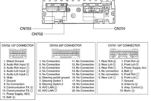
Okay, let's dive into the wiring of the radio in a 2000 Toyota Camry. Understanding this wiring diagram is invaluable whether you're replacing a faulty unit, upgrading to a modern head unit, troubleshooting speaker issues, or simply expanding your knowledge of automotive electrical systems. This article will provide you with a comprehensive overview, assuming you have some familiarity with basic automotive wiring and multimeter usage.
Purpose of the 2000 Toyota Camry Radio Wiring Diagram
The radio wiring diagram is essentially a roadmap of the electrical connections within your Camry's audio system. It shows you exactly how the radio (also known as the head unit), speakers, antenna, and other relevant components are interconnected. Without it, you're essentially guessing when trying to repair or modify the system. Here's why it's crucial:
- Repairing a Faulty Radio: If your radio suddenly stopped working, the diagram helps you trace the power supply, ground connections, and speaker outputs to identify potential points of failure.
- Replacing the Head Unit: A new head unit requires correct wiring connections for power, ground, illumination, remote turn-on (for amplifiers), and, of course, the speakers. The diagram allows you to match the wires from the new unit to the corresponding wires in your Camry's harness.
- Troubleshooting Speaker Problems: No sound from a speaker? The diagram lets you trace the speaker wire back to the head unit to check for breaks or shorts.
- Installing Aftermarket Amplifiers and Subwoofers: Adding external amplification necessitates tapping into the existing speaker wires or using RCA outputs (if available). The wiring diagram shows you where to safely tap into the appropriate signals.
- Understanding the System: Even if you're not planning any immediate repairs, understanding the wiring diagram helps you understand how the whole audio system is designed to work.
Key Specs and Main Parts
The 2000 Toyota Camry typically came with a single-DIN (single height) radio. Let's break down the main components and their functions within the context of the wiring diagram:
- Head Unit (Radio): The brain of the operation. It receives power, processes audio signals, and sends those signals to the speakers.
- Power Wire (+12V Constant): This wire provides constant power to the radio, allowing it to retain memory (presets, clock, etc.) even when the ignition is off. Usually a thicker gauge wire (e.g., 16-18 gauge).
- Ground Wire (GND): Provides the return path for the electrical current. A good, solid ground connection is absolutely critical for proper operation.
- Ignition Wire (+12V Switched): Supplies power to the radio only when the ignition is turned on. This wire turns the radio on and off with the car.
- Illumination Wire: Dimmer circuit connection. This wire connects to the vehicle's lighting circuit and dims the radio's display when the headlights are turned on.
- Antenna Wire: Connects the radio to the car's antenna, allowing it to receive radio signals.
- Speaker Wires (LF+, LF-, RF+, RF-, LR+, LR-, RR+, RR-): These wires carry the amplified audio signals from the radio to the speakers. LF stands for Left Front, RF for Right Front, LR for Left Rear, and RR for Right Rear. Each speaker requires a positive (+) and a negative (-) wire.
- Remote Turn-On (Amplifier): This wire provides a +12V signal when the radio is turned on. Its purpose is to trigger an external amplifier to turn on and off simultaneously with the radio.
Understanding the Wiring Diagram Symbols
Wiring diagrams use standardized symbols to represent components and connections. Here's a breakdown of common symbols you'll encounter in a 2000 Camry radio wiring diagram:
- Solid Lines: Represent wires. Thicker lines often indicate wires carrying higher current (like the power and ground wires).
- Dashed Lines: May represent shielded cables or wires that are part of a larger harness and not directly connected to the radio.
- Circles with Numbers Inside: Often indicate connector pin numbers. These numbers help you identify which wire corresponds to which function within a connector.
- Color Codes: Wires are identified by color codes (e.g., BLU for Blue, RED for Red, GRN for Green, WHT for White, BLK for Black, YEL for Yellow). These codes are essential for correctly identifying and connecting wires. A typical color coding you might see is BLU/YEL, which means blue with a yellow stripe.
- Ground Symbol: Looks like an upside-down triangle or a series of horizontal lines decreasing in size. This symbol indicates a connection to the vehicle's chassis ground.
- Connectors: Represented by various shapes (rectangles, circles) indicating the type of connector used.
- Fuses: Shown as a zigzag line inside a rectangle. Indicates a fuse in the circuit to protect against overcurrent.
- Splices: A dot where two or more wires connect.
How the Radio Wiring Works
The radio wiring is a relatively straightforward system. The +12V constant wire keeps the radio's memory alive. When you turn the ignition on, the +12V switched wire provides power to the main circuitry, allowing the radio to function. The ground wire completes the circuit. Audio signals from the radio's amplifier are sent to the speakers via the speaker wires (LF+, LF-, RF+, RF-, LR+, LR-, RR+, RR-). The antenna wire picks up radio signals, and the illumination wire dims the display when the headlights are on.
Let's consider an example: You want to install a new head unit. You'll need to identify the following wires on both the Camry's wiring harness and the new head unit's wiring harness:
- +12V Constant
- Ground
- +12V Switched
- Illumination (if supported by the new head unit)
- Speaker Wires (all eight)
- Antenna Connector
- Remote Turn-On (if connecting an amplifier)
Using the wiring diagram for your 2000 Camry, you'll match the color codes and functions of each wire from the Camry's harness to the corresponding wire on the new head unit's harness. You'll then connect them using crimp connectors, solder and heat shrink, or other suitable wiring methods. Properly insulate all connections to prevent shorts.
Real-World Use: Basic Troubleshooting Tips
Here are some common troubleshooting scenarios and how the wiring diagram can help:
- Radio Not Turning On: Check the +12V constant and +12V switched wires with a multimeter to ensure they are receiving power. Also, check the ground connection. Refer to the diagram to locate the fuse(s) associated with the radio circuit and check if they are blown.
- No Sound From One Speaker: Use the wiring diagram to trace the speaker wires from the head unit to the speaker. Check for breaks, shorts, or loose connections. Use a multimeter to check the speaker wire for continuity.
- Dim Radio Display: Verify that the illumination wire is properly connected and that the vehicle's dimmer switch is functioning correctly.
- Poor Radio Reception: Check the antenna connection at the back of the radio and the antenna base on the car. Ensure the antenna wire isn't damaged.
Safety Precautions
Working with automotive electrical systems can be dangerous. Always disconnect the negative terminal of the battery before working on any wiring. This prevents accidental shorts and potential damage to your vehicle's electrical system. Be especially careful when working around the airbag system. Incorrect wiring or accidental shorts can trigger the airbags, causing serious injury. If you are not comfortable working with electrical systems, consult a qualified professional.
Important Note: Incorrectly wiring the radio can damage the head unit, the vehicle's electrical system, or both. Double-check all connections before turning on the ignition. Pay close attention to polarity (+ and -) when connecting speaker wires. Reversing the polarity can cause the speakers to sound distorted or out of phase.
Remember, this article provides a general overview. Specific wiring configurations may vary slightly depending on the trim level and options of your 2000 Toyota Camry. Always refer to the correct wiring diagram for your specific vehicle.
We have a copy of the wiring diagram available for download. It's a detailed PDF file that will provide you with all the information you need. Download it now and good luck with your project!