2001 Chevy Astro Purge Valve Location Diagram
For the seasoned DIY mechanic tackling emission control issues on a 2001 Chevy Astro, understanding the evaporative emission (EVAP) system is crucial. And at the heart of that system is the purge valve. This article focuses on the 2001 Chevy Astro purge valve location diagram, explaining its purpose, key components, functionality, troubleshooting, and safety considerations. We'll treat this as if you're a savvy DIYer who wants to get the job done right.
Purpose of the Purge Valve Location Diagram
The 2001 Chevy Astro purge valve location diagram serves as your roadmap to the EVAP system. It's essential for several reasons:
- Diagnosis and Repair: Accurately locating the purge valve is the first step in diagnosing EVAP-related problems, such as trouble codes P0440, P0441, P0442, P0446, and others. These codes often point to leaks or malfunctions within the EVAP system, and the purge valve is a common culprit.
- Component Replacement: When replacing a faulty purge valve, the diagram ensures you're working on the correct component and know how to properly disconnect and reconnect hoses and electrical connectors.
- System Understanding: Studying the diagram helps you understand the overall layout and interaction of the EVAP system components, enabling you to make more informed decisions about repairs and modifications.
- Preventing Damage: Incorrectly disconnecting or reconnecting components can lead to further damage to the EVAP system or even other engine components. The diagram guides you through the process safely and accurately.
Basically, this diagram saves you time, money, and potential headaches by providing a clear visual representation of the system.
Key Specs and Main Parts
The 2001 Chevy Astro's EVAP system, including the purge valve, is designed to prevent fuel vapors from escaping into the atmosphere. Here are the main components you'll typically find on the diagram:
- Fuel Tank: The source of fuel vapors.
- Charcoal Canister: This canister stores the fuel vapors until the engine is ready to burn them. It contains activated charcoal which absorbs the hydrocarbons.
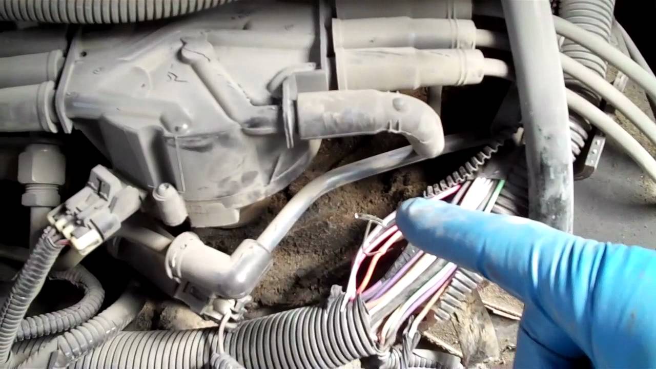
- Purge Valve (also known as the Canister Purge Solenoid Valve): This electronically controlled valve regulates the flow of fuel vapors from the charcoal canister to the engine intake manifold. This is the star of our show!
- Vent Valve: Allows fresh air to enter the EVAP system when the purge valve is open, preventing a vacuum from forming in the fuel tank.
- Fuel Tank Pressure Sensor (FTP): Monitors the pressure within the fuel tank, providing feedback to the PCM (Powertrain Control Module).
- EVAP Hoses and Lines: Connect all the components, carrying fuel vapors and air.
- PCM (Powertrain Control Module): The computer that controls the purge valve operation based on engine conditions.
The purge valve itself is typically a small, cylindrical solenoid valve. It has an electrical connector and two vacuum hose connections. The specifications, such as the resistance across the solenoid terminals, are vital for testing its functionality.
Symbols and Diagram Conventions
Understanding the symbols used in the diagram is key to interpreting it correctly. Here's a breakdown of common conventions:
- Solid Lines: Generally represent vacuum hoses or fuel vapor lines. Their thickness may indicate the hose diameter.
- Dotted Lines: Often represent electrical wiring or control signals.
- Colors: While not always present, colors can differentiate between different types of lines or hoses. For example, a red line might indicate a fuel line, while a blue line might indicate a vacuum line. Consult the diagram's legend for specific color coding.
- Component Symbols: Each component, such as the purge valve, charcoal canister, and FTP sensor, will have a specific symbol. These symbols are usually labeled with the component's name.
- Arrows: Indicate the direction of flow of fuel vapors or air.
- Ground Symbols: Indicate a ground connection for electrical components.
Pay close attention to the diagram's legend or key. It will provide specific definitions for each symbol and color used.
How It Works
The EVAP system, controlled by the PCM, prevents fuel vapors from escaping into the atmosphere. Here's how the purge valve plays its part:
- Vapor Collection: Fuel vapors from the fuel tank are routed to the charcoal canister, where they are absorbed by the activated charcoal.
- PCM Activation: When the engine reaches operating temperature and meets certain load conditions, the PCM sends a signal to the purge valve.
- Purge Valve Operation: The purge valve opens, allowing manifold vacuum to draw fuel vapors from the charcoal canister into the engine's intake manifold. These vapors are then burned along with the air-fuel mixture.
- Controlled Release: The PCM precisely controls the opening and closing of the purge valve to regulate the amount of fuel vapor entering the engine. This prevents the air-fuel mixture from becoming too rich.
- Closed Loop Feedback: The PCM monitors the fuel trims (adjustments to the air-fuel mixture) using the oxygen sensors. If the fuel trims are excessively positive (indicating a lean condition), the PCM may adjust the purge valve operation to compensate.
The purge valve is essentially a precisely controlled leak that allows the engine to burn fuel vapors that would otherwise be released into the atmosphere. It only operates under specific conditions to avoid negatively impacting engine performance.
Real-World Use: Basic Troubleshooting Tips
Here are some basic troubleshooting tips related to the purge valve, making use of your newfound understanding of the diagram:
- Check for Vacuum Leaks: Examine the hoses connected to the purge valve for cracks, leaks, or loose connections. Vacuum leaks can cause EVAP system codes and poor engine performance.
- Test the Purge Valve: Disconnect the electrical connector and use a multimeter to measure the resistance across the solenoid terminals. Compare the reading to the specifications in the service manual. An open or shorted circuit indicates a faulty valve.
- Actuate the Valve: Apply 12V power to the purge valve terminals (momentarily!) to see if it clicks open and closed. You should be able to blow through the valve when it's open. If it doesn't click or allow airflow when activated, it's likely faulty.
- Scan for Trouble Codes: Use an OBD-II scanner to check for EVAP-related trouble codes. These codes can provide valuable clues about the source of the problem. Common codes include P0440, P0441, P0442, P0446, P0455, P0456, etc.
- Smoke Test: A smoke test can help locate leaks in the EVAP system. Introduce smoke into the system and look for areas where smoke is escaping. This is a great way to find leaks in hoses, fittings, and the fuel tank.
- Check the FTP Sensor: A faulty FTP sensor can cause false EVAP codes. Use a scan tool to monitor the FTP sensor reading and compare it to the expected value.
Remember that a thorough diagnosis often requires a combination of visual inspection, electrical testing, and scan tool data analysis.
Safety Considerations
Working on the EVAP system involves handling fuel vapors, so safety is paramount. Here are some key safety precautions:
- Work in a Well-Ventilated Area: Fuel vapors are flammable and can be harmful to breathe. Ensure adequate ventilation when working on the EVAP system.
- Disconnect the Battery: Disconnect the negative battery cable before working on any electrical components, including the purge valve. This prevents accidental shorts and electrical shocks.
- Avoid Open Flames: Keep open flames, sparks, and sources of ignition away from the work area.
- Wear Safety Glasses: Protect your eyes from fuel splashes and debris.
- Dispose of Fuel-Soaked Rags Properly: Fuel-soaked rags can spontaneously combust. Store them in a sealed metal container and dispose of them properly.
- Be careful when disconnecting fuel lines. Relieve pressure from the fuel system first, and be prepared to catch any spilled fuel.
The fuel system operates under pressure. Always relieve the pressure before disconnecting any fuel lines or components.
By carefully studying the 2001 Chevy Astro purge valve location diagram and following these guidelines, you can confidently diagnose and repair EVAP system problems on your vehicle. Remember to always consult the service manual for specific instructions and torque specifications.
You can download the 2001 Chevy Astro purge valve location diagram from our resource library, which includes additional supporting material for your reference.