
2001 Dodge Ram 1500 Vacuum Line Diagram
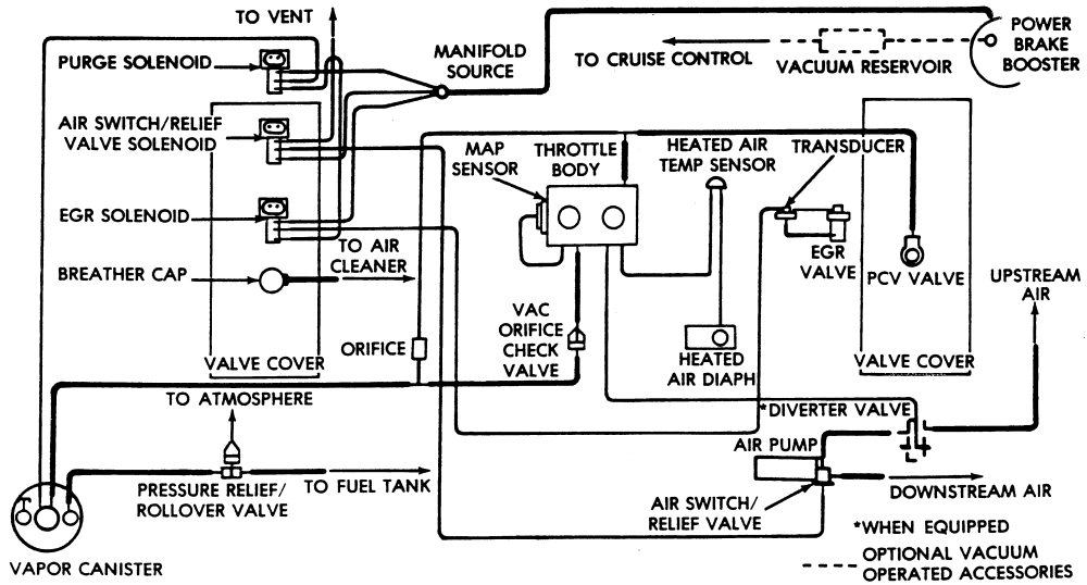
The 2001 Dodge Ram 1500, a workhorse of its era, relies on a complex vacuum system to manage various engine and accessory functions. Understanding the vacuum line diagram is crucial for proper diagnosis and repair of issues ranging from poor engine performance to malfunctioning HVAC controls. This article will break down the intricacies of this diagram, helping you, the experienced DIYer, navigate the system like a pro.
Purpose of the Vacuum Line Diagram
Why bother with a vacuum line diagram? The answer is simple: it's your roadmap to understanding and fixing vacuum-related problems. These diagrams are invaluable for:
- Diagnosis: Identifying leaks, blockages, or incorrect connections when encountering issues like rough idling, poor acceleration, or malfunctioning emissions controls.
- Repairs: Ensuring correct reassembly of vacuum lines after maintenance or repairs. Replacing brittle or cracked lines with confidence.
- Learning: Gaining a deeper understanding of how various engine components and accessories interact through the vacuum system.
- Modifications: Making informed decisions when modifying the engine or related systems, ensuring compatibility and avoiding vacuum-related complications.
Imagine trying to replace a tangled fishing line without knowing how it's supposed to be strung through the guides – that's what working on vacuum lines without a diagram is like. It's a recipe for frustration and potential damage.
Key Specs and Main Parts
The 2001 Dodge Ram 1500 (especially with the 5.2L and 5.9L Magnum engines) typically features a vacuum system that controls the following key components:
- Intake Manifold Vacuum Source: This is the primary source of vacuum for the entire system. It's a crucial point to check for leaks or blockages.
- PCV (Positive Crankcase Ventilation) Valve: Manages crankcase pressure and emissions. A malfunctioning PCV valve or associated hoses can significantly impact engine performance.
- EGR (Exhaust Gas Recirculation) Valve: Reduces NOx emissions by recirculating a portion of exhaust gas back into the intake manifold. Vacuum controls its operation.
- EVAP (Evaporative Emission Control) System: Prevents fuel vapors from escaping into the atmosphere. Vacuum is used to purge the EVAP canister.
- HVAC (Heating, Ventilation, and Air Conditioning) Controls: Vacuum actuators control the blend doors and mode doors, directing airflow within the cabin. A vacuum leak here often results in the inability to switch between defrost, vent, and floor settings.
- MAP (Manifold Absolute Pressure) Sensor: Measures the pressure in the intake manifold, providing crucial data to the engine control unit (ECU) for fuel and ignition timing calculations. While the MAP sensor itself is electronic, it's directly affected by vacuum.
- Brake Booster: Uses engine vacuum to assist braking. A leak in the brake booster vacuum line can lead to hard braking.
Key specs to keep in mind include hose diameter (typically 1/4" or 5/32") and material. Always use vacuum-rated hose for replacements, as standard rubber hose will collapse under vacuum.
Understanding the Symbols in the Diagram
Vacuum line diagrams aren't just a jumble of lines; they use specific symbols and conventions to convey information. Here's a breakdown:
- Lines: Different types of lines can represent different types of vacuum lines. Sometimes solid lines represent direct vacuum connections, while dashed lines may indicate a connection through a check valve or other component.
- Colors: Many diagrams use color-coding to differentiate between vacuum lines serving different systems. Common colors include black, red, green, and blue. Consult the specific diagram for your 2001 Ram 1500 to understand the color codes used.
- Arrows: Arrows indicate the direction of vacuum flow. This is particularly important when dealing with check valves.
- Components: Symbols represent various components within the vacuum system. These can include vacuum reservoirs (small tanks that store vacuum), check valves (allow vacuum to flow in one direction only), solenoids (electrically controlled valves), and vacuum actuators.
- Abbreviations: Pay close attention to abbreviations like "PCV," "EGR," "EVAP," and "MAP." These are crucial for identifying specific components.
Understanding these symbols is like learning a new language. Once you grasp the basics, the diagram becomes much easier to interpret.
How It Works: The Vacuum System in Action
The engine's intake manifold creates a vacuum as the pistons move downward during the intake stroke. This vacuum is then harnessed to power various systems. Let's consider a few examples:
- PCV System: Vacuum draws crankcase gases through the PCV valve and into the intake manifold, where they are burned. This prevents pressure buildup in the crankcase and reduces emissions.
- EGR System: When the ECU commands the EGR valve to open (based on engine load and temperature), vacuum is applied to the EGR valve diaphragm, causing it to open and allow exhaust gas to flow into the intake manifold.
- HVAC System: Vacuum actuators control the position of blend doors and mode doors. When you select a different HVAC mode (e.g., defrost), the control panel directs vacuum to the appropriate actuator, which moves the door to the desired position.
The key takeaway is that a vacuum leak anywhere in the system can disrupt the operation of multiple components, leading to a variety of problems.
Real-World Use: Troubleshooting Tips
Here are some basic troubleshooting tips using the vacuum line diagram:
- Visual Inspection: Start by visually inspecting all vacuum lines for cracks, breaks, or disconnections. Pay particular attention to lines near heat sources or areas where they may rub against other components.
- Vacuum Gauge: Use a vacuum gauge to check the vacuum level at various points in the system. A low vacuum reading can indicate a leak.
- Spray Test: With the engine running, spray small amounts of carburetor cleaner or starting fluid around vacuum lines and connections. If the engine speed changes, you've likely found a leak. Caution: Use this method sparingly and avoid spraying near ignition components to prevent fire.
- Component Testing: Test individual vacuum-operated components (e.g., EGR valve, PCV valve) to ensure they are functioning properly. The diagram will help you identify the correct vacuum lines to disconnect and test.
- Smoke Test: For difficult-to-find leaks, a smoke test can be invaluable. A smoke machine injects smoke into the vacuum system, revealing leaks as smoke escapes.
Safety Considerations
Working with the vacuum system generally isn't inherently dangerous, but there are a few precautions to keep in mind:
- Hot Engine Components: Be careful when working around hot engine components, such as the exhaust manifold.
- Flammable Liquids: As mentioned earlier, use carburetor cleaner or starting fluid sparingly when searching for leaks, and avoid spraying near ignition components.
- Brake Booster: A faulty brake booster can significantly reduce braking power. If you suspect a problem with the brake booster vacuum line, have the braking system inspected by a qualified mechanic.
Remember, safety always comes first. If you're unsure about any aspect of the repair, consult a professional mechanic.
By understanding the purpose, components, symbols, and operation of the 2001 Dodge Ram 1500 vacuum system, you'll be well-equipped to diagnose and repair vacuum-related problems, keeping your truck running smoothly for years to come.
We have the 2001 Dodge Ram 1500 Vacuum Line Diagram file ready for you to download. This detailed diagram provides a visual aid that will greatly assist you in your diagnostic and repair work. Use it in conjunction with the information in this article for a comprehensive understanding of your vehicle's vacuum system.