2001 Ford Explorer Fuse Box Diagram Under Hood
Welcome, fellow gearheads! Let's dive into a critical component of your 2001 Ford Explorer: the under-hood fuse box. This article will be your comprehensive guide to understanding its diagram, empowering you to diagnose electrical issues, perform modifications, and generally become more intimately acquainted with your vehicle's inner workings. Think of this as decoding a vital electrical map for your trusty Explorer.
Purpose: Your Electrical Troubleshooting Key
Why is understanding the under-hood fuse box diagram so important? Simple: it's your first line of defense when dealing with electrical problems. Fuses are designed to protect sensitive circuits from overcurrent (too much electricity flowing through a wire). When a circuit draws excessive current, the fuse "blows," breaking the circuit and preventing damage to expensive components. A blown fuse is often the culprit behind a seemingly complex electrical malfunction. By consulting the fuse box diagram, you can quickly identify the fuse responsible for a specific circuit (e.g., headlights, wipers, radio) and replace it. This can save you time, money, and a trip to the mechanic.
Beyond basic repairs, understanding the fuse box layout is crucial for modifications. Thinking about installing aftermarket lights, a new stereo system, or a trailer brake controller? You'll need to tap into the Explorer's electrical system safely and correctly. The diagram helps you identify appropriate circuits, ensuring you don't overload anything and potentially cause a fire or damage.
Key Specs and Main Parts
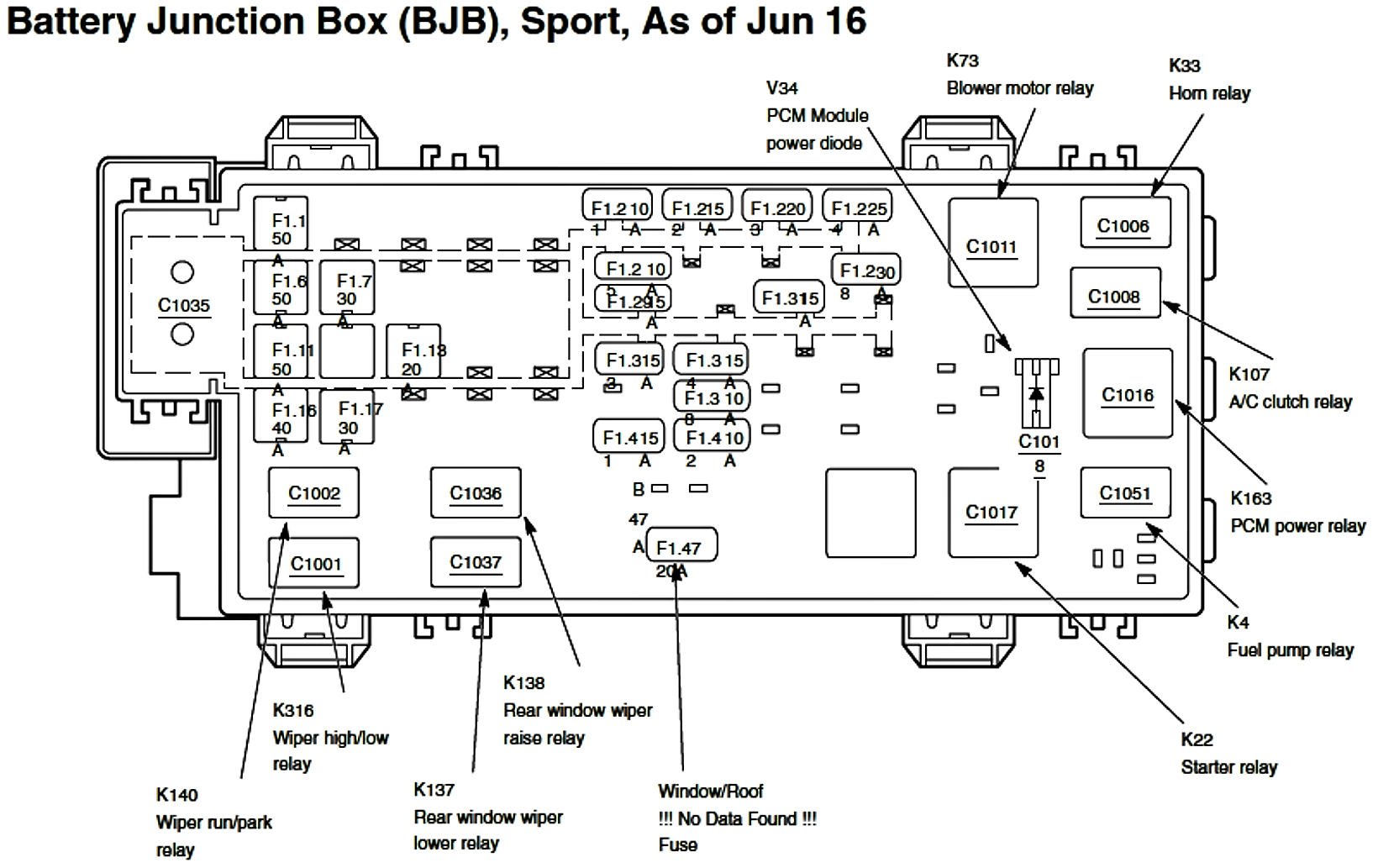
The 2001 Ford Explorer's under-hood fuse box is typically located on the driver's side of the engine compartment, near the battery. It's housed in a black plastic enclosure with a removable cover. The inside of the cover usually has a printed diagram showing the fuse locations and their corresponding circuits. The diagram is crucial; without it, you're essentially guessing which fuse controls what.
Main components you'll find:
- Fuses: These are the sacrificial links in the circuit, rated in amperes (amps, A). Common ratings include 5A, 10A, 15A, 20A, 25A, 30A, and higher. The amperage rating indicates the maximum current the fuse can handle before blowing.
- Relays: These are electromechanical switches that control high-current circuits using a low-current signal. Think of them as amplifiers for electrical signals. Relays are often used to control headlights, the fuel pump, and other high-draw components.
- Circuit Breakers: Similar to fuses, but they can be reset after tripping. Circuit breakers are often used for circuits that experience occasional overloads, such as power windows.
- Fuse Puller: A small plastic tool (often integrated into the fuse box cover) used to safely remove fuses without damaging them.
- Terminal Blocks: These provide connection points for wiring harnesses.
Symbols: Decoding the Electrical Language
The fuse box diagram uses a combination of lines, colors, and icons to represent the different components and their functions. Understanding these symbols is key to interpreting the diagram correctly.
- Lines: Solid lines represent wires connecting components. Dashed lines might indicate ground connections or connections to other parts of the electrical system.
- Colors: Wires are color-coded according to their function. While the exact color codes can vary slightly, common colors include red (power), black (ground), and various other colors to indicate specific circuits (e.g., blue for headlights, yellow for ignition). The diagram *should* have a legend explaining the color codes.
- Icons: These represent the components protected by the fuse. You might see icons for:
- Headlights
- Windshield wipers
- Radio
- Power windows
- Power locks
- Fuel pump
- Engine control unit (ECU)
- Anti-lock braking system (ABS)
- Air conditioning (A/C)
Each fuse location is typically labeled with a number and a brief description of the circuit it protects. For example, "Fuse 22 - Headlights (15A)" indicates that fuse number 22 protects the headlight circuit and is rated at 15 amps.
How It Works: A Simplified Electrical Flow
Imagine the electrical system as a network of roads. The battery is the power source, providing the initial "energy." Wires are the roads, carrying the electricity to different components. Fuses are like toll booths, controlling the flow of traffic (electricity). If too much traffic tries to pass through at once (overcurrent), the toll booth closes (the fuse blows), preventing damage to the road (the circuit and its components).
When you turn on a switch (e.g., the headlight switch), you complete a circuit, allowing electricity to flow from the battery, through the switch, through the fuse, and to the headlights. If a short circuit occurs (e.g., a wire rubs against the chassis and creates a direct path to ground), the resistance drops dramatically, causing a surge of current. This surge exceeds the fuse's amperage rating, causing it to blow and break the circuit.
Relays work similarly but are used to control circuits that require higher currents. A low-current signal from a switch activates the relay, which then closes a separate circuit, allowing high current to flow to the component (e.g., the fuel pump).
Real-World Use: Basic Troubleshooting Tips
Here's how to use the fuse box diagram for troubleshooting:
- Identify the problem: Determine which component is not working (e.g., the radio is dead).
- Consult the diagram: Locate the fuse associated with that component.
- Inspect the fuse: Visually inspect the fuse. A blown fuse will typically have a broken filament (the thin wire inside the fuse).
- Test the fuse (optional): Use a multimeter set to continuity mode to test the fuse. A good fuse will have continuity (the multimeter will beep or show a reading close to zero ohms). A blown fuse will have no continuity (the multimeter will show an open circuit).
- Replace the fuse: Use a fuse of the same amperage rating. Never use a fuse with a higher amperage rating, as this can damage the circuit.
- Test the circuit: After replacing the fuse, test the component to see if it's working.
If the fuse blows again immediately after replacement: This indicates a short circuit or an overload in the circuit. Further diagnosis is required to find the source of the problem. This might involve checking wiring harnesses for damage, inspecting components for shorts, or consulting a wiring diagram.
Safety: Handle with Care!
Working with the electrical system can be dangerous. Always disconnect the negative terminal of the battery before working on the fuse box or any electrical component. This will prevent accidental short circuits and shocks.
Be especially careful when working with circuits related to:
- Airbags: These circuits can be triggered by static electricity or improper handling. Disconnect the battery and wait at least 10 minutes before working on airbag-related components.
- Fuel pump: Fuel is flammable. Avoid sparks or open flames when working on the fuel pump circuit.
- High-current circuits: These circuits can deliver a powerful shock. Always use insulated tools and avoid touching bare wires.
Always double-check your work and consult a qualified mechanic if you're unsure about anything. Electricity is not something to take lightly.
We have the complete, high-resolution fuse box diagram for the 2001 Ford Explorer under the hood available for download. This will be an invaluable resource for your troubleshooting and modification projects. This document provides a clear and detailed layout of all fuses, relays, and their corresponding circuits. With this at your disposal, you'll be well-equipped to tackle any electrical issue with confidence.