2001 Ford Explorer Sport Fuse Panel Diagram
If you're tackling electrical work on a 2001 Ford Explorer Sport, understanding its fuse panel diagram is absolutely crucial. Whether you're diagnosing a faulty circuit, adding aftermarket accessories, or simply trying to understand the electrical system, this diagram is your roadmap. This article breaks down the 2001 Explorer Sport's fuse panel, explaining its components, symbols, and practical applications.
Purpose of the Fuse Panel Diagram
The fuse panel diagram isn't just a decorative piece of paper; it's an essential diagnostic and repair tool. Its primary purposes include:
- Troubleshooting Electrical Problems: When a component stops working (e.g., a taillight, the radio, or the power windows), the diagram helps you quickly locate the relevant fuse.
- Identifying Circuit Protection: Understanding which fuse protects which circuit helps prevent further damage during repairs or modifications.
- Adding Aftermarket Accessories: If you're installing a new stereo, fog lights, or other accessories, the diagram helps you identify safe and appropriate circuits to tap into.
- Preventing Electrical Fires: Knowing the correct fuse amperage (current rating) is vital for preventing overloads that can lead to dangerous electrical fires.
- Learning the Vehicle's Electrical System: Studying the diagram gives you a deeper understanding of how the Explorer Sport's electrical system is designed and functions.
Key Specs and Main Parts
The 2001 Ford Explorer Sport, like most vehicles, has two primary fuse locations:
- Interior Fuse Panel: Typically located under the dashboard, on the driver's side (usually behind a small access panel). This panel houses fuses for interior components like the radio, power windows, interior lights, and instrument panel.
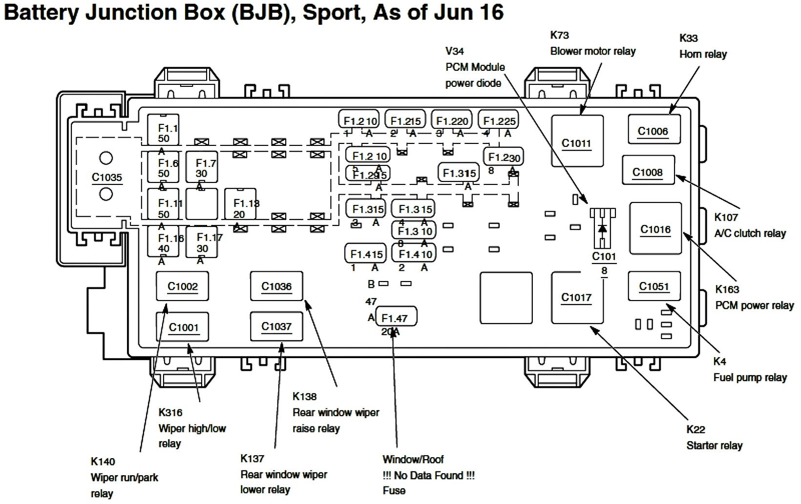
- Under-Hood Power Distribution Box (PDB): Located in the engine compartment, this box contains fuses and relays for higher-current systems like the headlights, starter motor, fuel pump, and ABS system. The PDB often uses Maxi-fuses – larger fuses designed to handle higher amperage loads.
Key specifications to be aware of when dealing with your fuse panel include:
- Amperage Rating (Amps): Each fuse has a specific amperage rating, indicating the maximum current it can handle before blowing (breaking the circuit). These ratings are usually printed on the fuse itself (e.g., 5A, 10A, 15A, 20A, 25A, 30A). Never replace a fuse with one of a higher amperage rating, as this can lead to overheating and electrical fires.
- Fuse Type: The 2001 Explorer Sport primarily uses blade-type fuses (also called spade fuses). These are small, rectangular fuses with two exposed metal blades that plug into the fuse panel. There are also some older cylindrical glass fuses in some applications. The Maxi-fuses in the PDB are typically larger blade-type fuses.
Symbols and Lines in the Diagram
Fuse panel diagrams use symbols and lines to represent different components and connections. Here's a breakdown of common symbols:
- Fuses: Typically represented by a small rectangle with a zig-zag line through it. The amperage rating is usually indicated next to the symbol.
- Relays: Shown as a square or rectangle with internal symbols representing the coil and switch contacts. Relays are electromechanical switches that use a small electrical current to control a larger current.
- Grounds: Represented by a triangle or a series of lines decreasing in length. Grounds are the return path for electrical current.
- Wires: Represented by straight lines connecting components. The color of the wire may be indicated on the diagram using abbreviations (e.g., BLU for blue, RED for red, GRN for green, BLK for black, WHT for white, YEL for yellow).
- Connectors: Indicated by a circle or a box. These show where wires are connected to each other.
- Power Source: Usually indicated with a plus sign (+) or "BATT" (for battery).
Lines on the Diagram:
- Solid Lines: Represent direct electrical connections.
- Dashed Lines: May indicate a connection that is optional or only present in certain configurations (e.g., with a specific trim level or option package).
How It Works: A Simplified Explanation
The fuse panel acts as a central distribution point for electrical power. The battery provides the initial power source. This power is then routed through the fuse panel to various components throughout the vehicle.
Each circuit in the vehicle is protected by a fuse. When the current in a circuit exceeds the fuse's amperage rating (due to a short circuit, overload, or other fault), the fuse's internal element melts, breaking the circuit and stopping the flow of electricity. This protects the wiring and components from damage. Think of a fuse as a sacrificial link designed to fail before other, more expensive parts.
Relays are used to control high-current circuits with a low-current signal. For example, the headlight switch might activate a relay that then supplies power to the headlights. This allows the switch to be smaller and handle less current. The relay is essential because the headlight switch doesn't need to handle the power required for headlights, preventing it from getting damaged.
Real-World Use: Basic Troubleshooting Tips
Here's how you can use the fuse panel diagram for basic troubleshooting:
- Identify the Problem: Determine which component is not working.
- Consult the Diagram: Use the diagram to locate the fuse that protects the circuit for the faulty component. The diagram will often be located in the owner's manual, on the inside of the fuse panel cover, or accessible online.
- Locate the Fuse: Find the fuse in the appropriate fuse panel (interior or under-hood).
- Inspect the Fuse: Visually inspect the fuse. If the element inside is broken or blackened, the fuse is blown. You can use a multimeter to check for continuity across the fuse terminals for more accuracy.
- Replace the Fuse: Replace the blown fuse with a new fuse of the same amperage rating. Never use a fuse with a higher amperage.
- Test the Component: After replacing the fuse, test the component to see if it now works.
- If the Fuse Blows Again: If the new fuse blows immediately, there is a short circuit or overload in the circuit. Further diagnosis is required to find and correct the underlying problem. This might involve checking wiring for damage, inspecting the component itself, or consulting a more detailed wiring diagram.
Safety Considerations
Working with electrical systems can be dangerous. Here are some important safety precautions:
- Disconnect the Battery: Before working on the fuse panel, disconnect the negative (-) battery cable to prevent accidental shorts or electrical shocks.
- Use Insulated Tools: Use tools with insulated handles to avoid electrical shocks.
- Never Bypass a Fuse: Never bypass a fuse with a wire or other conductive material. This eliminates the circuit protection and can lead to serious damage or fire.
- Be Careful Around High-Current Components: Be especially cautious around the under-hood power distribution box, as it contains high-current circuits that can deliver a powerful electrical shock.
- Know Your Limits: If you are not comfortable working with electrical systems, consult a qualified mechanic.
Special attention should be paid to components related to the SRS (Supplemental Restraint System), especially the airbag system. Tampering with these components can cause accidental airbag deployment, leading to serious injury. If you suspect an issue with your airbag system, seek professional assistance from a qualified technician.
We have the complete 2001 Ford Explorer Sport Fuse Panel Diagram available for download. This detailed diagram will provide you with the necessary information to diagnose and repair electrical issues effectively and safely.