2001 Ford Explorer Sport Trac Fuse Box Diagram
Alright, let's dive into the fuse box diagram for a 2001 Ford Explorer Sport Trac. Understanding this diagram is absolutely crucial, whether you're chasing down a pesky electrical gremlin, planning to tap into a circuit for a new accessory, or simply wanting to get more familiar with your vehicle's electrical system. Think of it as the roadmap to your Sport Trac's electrical arteries.
Why Bother with a Fuse Box Diagram?
The main purpose of knowing your fuse box layout boils down to these key areas:
- Troubleshooting Electrical Issues: If your headlights suddenly quit, your radio goes silent, or a window refuses to roll down, the first place to look is often the fuses. The diagram tells you exactly which fuse controls which circuit, saving you a ton of time and frustration.
- Safe Circuit Modification: Planning to install an aftermarket stereo, auxiliary lights, or a trailer brake controller? Knowing your fuse box allows you to tap into the correct power source safely and protect your new devices (and your vehicle's existing electrical system) with appropriate fusing. Improper wiring can lead to short circuits, fires, and damaged components – don't risk it.
- General Vehicle Knowledge: Understanding the layout helps you become a more informed owner, capable of performing basic maintenance and understanding the inner workings of your Sport Trac.
Key Specs and Main Parts of the 2001 Sport Trac Fuse Box
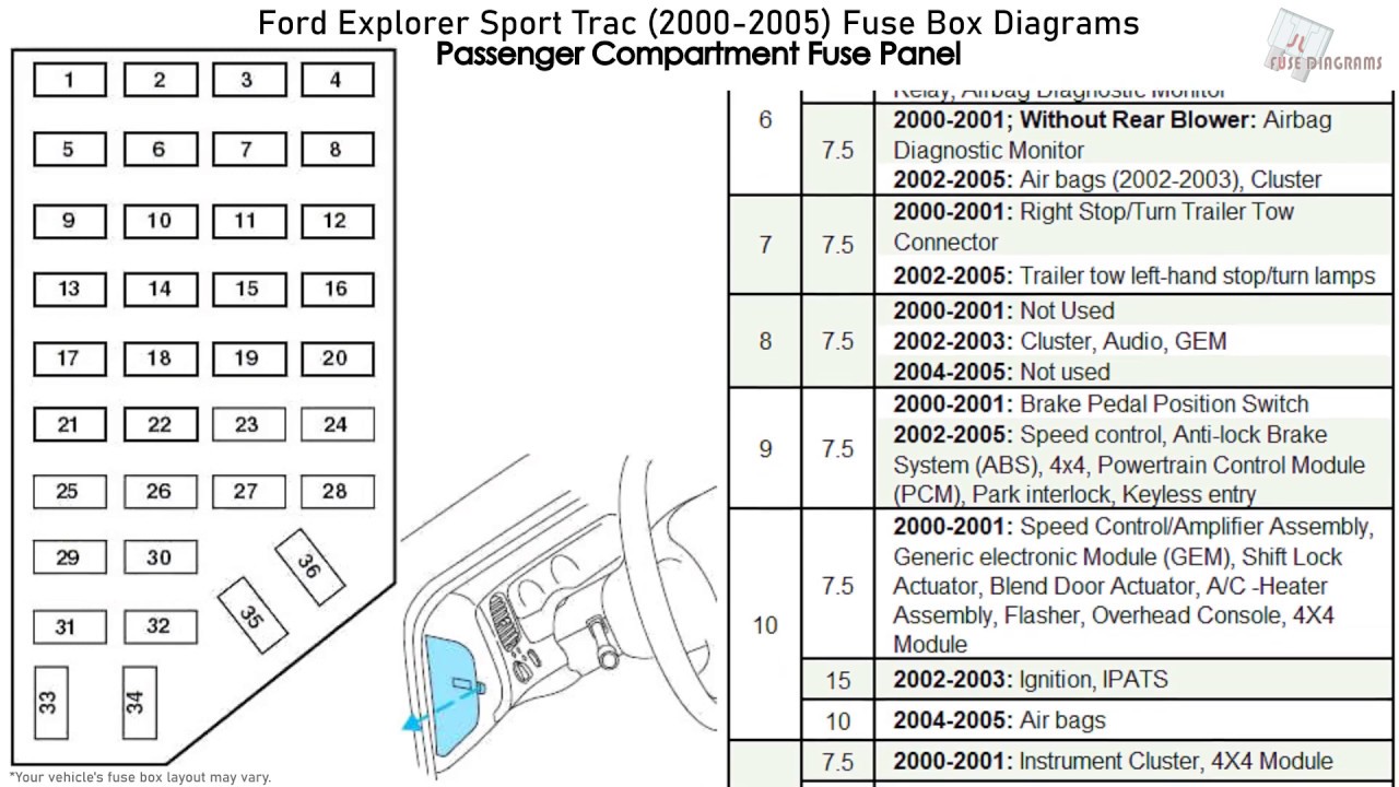
The 2001 Ford Explorer Sport Trac actually has two main fuse locations. It's important to be aware of both. One is located under the hood, typically near the battery, and the other is inside the cabin, usually under the dashboard on the driver's side. Each location houses different fuses and relays responsible for different vehicle systems.
- Under-Hood Fuse Box (Power Distribution Box): This box typically contains fuses and relays for high-current components like the starter motor, fuel pump, headlights, and the engine control unit (ECU). It's the primary distribution point for power coming from the battery.
- In-Cabin Fuse Box: This box handles lower-current circuits like the radio, interior lights, power windows, and the instrument cluster.
Key components you'll find in these boxes include:
- Fuses: These are sacrificial devices designed to protect circuits from overcurrent. They consist of a thin wire that melts and breaks the circuit when the current exceeds the fuse's rating (measured in Amperes, or Amps).
- Relays: These are electromechanical switches that allow a low-current circuit (controlled by a switch inside the cabin) to control a high-current circuit (like the headlights). They act as an intermediary, preventing excessive current from flowing through smaller switches.
- Circuit Breakers: Some circuits may use circuit breakers instead of fuses. Circuit breakers are resettable; they trip (open the circuit) when overloaded and can be reset manually or automatically once the overload is removed.
- Connectors and Terminals: These provide the physical connections between the fuses/relays and the wiring harness.
Decoding the Symbols on the Fuse Box Diagram
Understanding the symbols used on the fuse box diagram is crucial. Here's a breakdown of what you'll commonly encounter:
- Lines: Solid lines typically represent wires or conductors. Dashed lines may indicate ground connections or shielded wires. The thickness of the line may not necessarily indicate the wire gauge.
- Colors: Wiring diagrams use color codes to identify individual wires. For example, a wire might be labeled "RD/BK," meaning a red wire with a black stripe. A key on the diagram will explain these color codes. Common colors include red (RD), black (BK), blue (BL), green (GN), yellow (YE), white (WH), and brown (BN).
- Fuse Symbols: A standard fuse symbol is usually a small rectangle with a squiggly line inside. The diagram will also indicate the fuse amperage rating (e.g., 20A, 30A).
- Relay Symbols: Relay symbols typically show a coil (represented by a curved line) and a set of contacts that open or close when the coil is energized.
- Component Symbols: The diagram will include symbols for the various components connected to the circuits, such as headlights, motors, sensors, and switches. These symbols are often simplified representations of the actual components.
Important Note: Always refer to the specific diagram for your 2001 Sport Trac. Diagrams can vary slightly depending on the vehicle's options and trim level.
How the Fuse Box Works (The Electrical Flow)
The fuse box serves as a central distribution point for electrical power. Power from the battery flows through the main wiring harness to the fuse boxes (both under-hood and in-cabin). From there, the power is distributed to various circuits through individual fuses and relays. Each circuit is designed to power a specific component or group of components.
Here's a simplified example: Let's say you turn on your headlights. The headlight switch in the cabin sends a signal to a relay in the under-hood fuse box. The relay then closes, allowing power to flow from the battery, through a fuse (to protect the headlight circuit), and finally to the headlights, illuminating them.
If a short circuit occurs (e.g., a wire chafes against the chassis and creates a direct path to ground), the current in that circuit will surge. The fuse will then blow, interrupting the flow of current and preventing damage to the wiring and components.
Real-World Use: Basic Troubleshooting Tips
Here's how you can use the fuse box diagram for troubleshooting:
- Identify the Problem: Determine which component or system is malfunctioning (e.g., power windows not working).
- Consult the Diagram: Locate the fuse or relay associated with that component or system in the fuse box diagram.
- Inspect the Fuse: Visually inspect the fuse. If the thin wire inside is broken, the fuse is blown and needs to be replaced. You can also use a multimeter to test continuity across the fuse. A good fuse will show continuity (a reading of close to zero ohms).
- Replace the Fuse: Replace the blown fuse with a new fuse of the exact same amperage rating. Never use a fuse with a higher amperage rating, as this can damage the circuit and create a fire hazard.
- Test the System: After replacing the fuse, test the component or system to see if it's working properly.
- If the Fuse Blows Again: If the new fuse blows immediately or shortly after being replaced, it indicates a more serious problem, such as a short circuit or an overloaded circuit. You'll need to investigate the wiring and components in that circuit to find the source of the problem. This might involve using a multimeter to check for voltage and resistance readings, and visually inspecting the wiring for damage.
Safety First: Respecting the Electrical System
Working with automotive electrical systems can be dangerous if you're not careful. Here are some key safety precautions:
- Disconnect the Battery: Before working on any electrical components, always disconnect the negative terminal of the battery. This will prevent accidental short circuits and electrical shocks.
- Work in a Well-Lit Area: Good visibility is essential for avoiding mistakes.
- Use Insulated Tools: Use tools with insulated handles to protect yourself from electrical shock.
- Never Bypass Fuses: Never bypass a fuse with a piece of wire or any other conductive material. This eliminates the circuit protection and can lead to serious damage or fire.
- Be Cautious Around Airbags: Airbag systems are electrically activated and can be dangerous if handled improperly. If you're working near airbags, disconnect the battery and wait at least 30 minutes to allow the airbag system to discharge. Refer to your vehicle's service manual for specific airbag safety procedures.
- High-Current Circuits: Be particularly cautious around high-current circuits, such as the starter motor and alternator circuits. These circuits can deliver a significant electrical shock.
Specifically regarding the Sport Trac's fuse box, pay close attention to the relays controlling the fuel pump and ignition. These are critical components, and tampering with them could prevent the engine from starting or even cause damage.
Remember, if you're not comfortable working on electrical systems, it's always best to consult a qualified mechanic.
We've got the complete 2001 Ford Explorer Sport Trac fuse box diagram ready for you. You can download it to have it handy while you work. Good luck!