
2001 Ford F150 4.6 Vacuum Hose Diagram
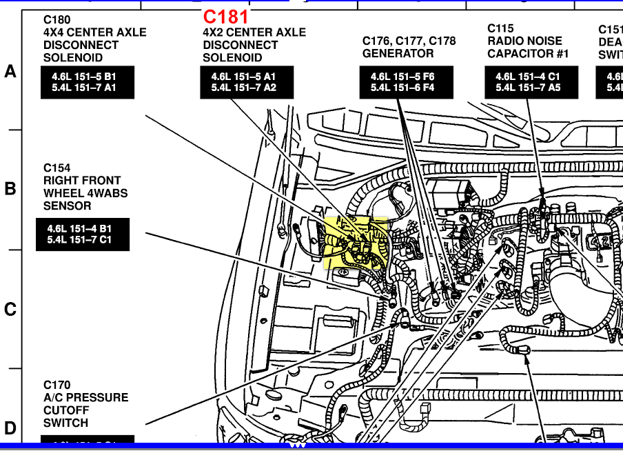
Alright, let's dive into the vacuum hose diagram for your 2001 Ford F150 with the 4.6L engine. This guide is designed for intermediate DIYers who aren't afraid to get their hands dirty but appreciate a clear explanation of what they're looking at. Vacuum lines are crucial for a smooth-running engine, and understanding their layout is essential for diagnostics, repairs, and even some performance modifications.
Purpose of the Vacuum Hose Diagram
Why bother with a vacuum hose diagram? Well, several reasons:
- Troubleshooting Engine Issues: Vacuum leaks are notorious for causing a multitude of problems, from rough idling and poor acceleration to reduced fuel economy and even failed emissions tests. The diagram helps you pinpoint the source of these leaks.
- Repair and Replacement: Over time, vacuum hoses become brittle, crack, or simply detach. The diagram guides you in replacing these hoses correctly.
- Understanding Engine Systems: Delving into the vacuum system provides a deeper understanding of how various engine components interact. This is particularly useful if you're interested in engine tuning or performance upgrades.
- Ensuring Proper Functionality: A properly functioning vacuum system is essential for components like the power brakes, climate control system, and emissions control devices.
Key Specs and Main Parts
Before we delve into the diagram itself, let's outline the essential components and their roles in the 2001 F150 4.6L vacuum system. Bear in mind there can be minor variations depending on specific sub-models and options.
- Vacuum Reservoir (often called a 'coffee can'): This spherical or cylindrical container stores vacuum created by the engine. It provides a consistent vacuum source when engine vacuum fluctuates (e.g., during hard acceleration).
- Vacuum Pump (if equipped): Some F150s, particularly those with certain emissions packages, might have an electric vacuum pump to supplement engine vacuum.
- PCV (Positive Crankcase Ventilation) Valve: This valve regulates the flow of crankcase gases back into the intake manifold. It's crucial for emissions control and preventing pressure buildup in the engine.
- EGR (Exhaust Gas Recirculation) Valve: The EGR valve reduces NOx (oxides of nitrogen) emissions by recirculating a portion of exhaust gas back into the intake manifold. It is typically vacuum-operated.
- EVAP (Evaporative Emission Control) System: This system prevents fuel vapors from escaping into the atmosphere. It involves components like the fuel tank, charcoal canister, purge valve, and vent valve, all interconnected by vacuum lines.
- Vacuum Brake Booster: Uses engine vacuum to assist the driver in applying the brakes.
- HVAC System: Vacuum actuators control the blend doors and mode doors that direct airflow within the cabin for heating, cooling, and ventilation.
- Intake Manifold: The source of the vacuum itself.
Symbols, Lines, and Colors on the Diagram
Understanding the conventions used on the vacuum hose diagram is crucial for interpreting it correctly. While specific diagram styles can vary, here are some common elements:
- Solid Lines: Typically represent vacuum hoses or tubing.
- Dashed Lines: May indicate electrical wiring or control lines related to vacuum-operated components.
- Arrows: Indicate the direction of vacuum flow.
- Colors: While not always present, color-coding can help differentiate between different vacuum circuits. For example, one color might represent the EVAP system, while another represents the brake booster circuit. Consult the specific legend on your diagram.
- Symbols: Specific symbols will represent vacuum switches, check valves (allow flow in only one direction), and vacuum actuators. The diagram should have a key that identifies each symbol. A T-fitting, will be shown as a "T" shape and a check valve will be shown as a short line with an arrow pointing in the direction of flow.
- Component Labels: Each component will be labeled with an abbreviation (e.g., "PCV," "EGR," "VAC RES").
How the Vacuum System Works
The 4.6L engine generates vacuum within the intake manifold as the pistons move down during the intake stroke. This vacuum is then distributed through a network of hoses to various components that rely on vacuum for their operation. The degree of vacuum varies depending on engine load and speed. For example, vacuum is highest at idle and decreases as you accelerate.
The PCV valve uses vacuum to draw crankcase gases into the intake manifold, where they are burned. The EGR valve opens in response to vacuum signals to allow exhaust gas to flow back into the intake. The EVAP system uses vacuum to purge fuel vapors from the charcoal canister and burn them in the engine. The brake booster uses the vacuum differential to provide power assist when the brake pedal is depressed.
Real-World Use: Troubleshooting Tips
Here are some practical tips for using the vacuum hose diagram to diagnose problems:
- Visual Inspection: Start by visually inspecting all vacuum hoses for cracks, breaks, or disconnections. Pay close attention to areas where the hoses connect to fittings.
- Vacuum Gauge: A vacuum gauge can be connected to a vacuum port on the intake manifold to measure engine vacuum. A low or fluctuating vacuum reading can indicate a leak.
- Smoke Test: A smoke test involves injecting smoke into the vacuum system to identify leaks. The smoke will escape from any cracks or loose connections.
- Listen for Hissing: A hissing sound can indicate a vacuum leak. Use a length of hose as a stethoscope to pinpoint the source of the hiss.
- Check Valve Operation: Ensure that check valves are functioning correctly by blowing through them. They should only allow airflow in one direction.
- Use the Diagram: When replacing hoses, use the diagram to ensure you route them correctly. Incorrect routing can lead to performance problems or even damage to components.
Safety Considerations
Working on the vacuum system involves handling components that can be hot or contain flammable fluids. Here are some important safety precautions:
- Work on a Cool Engine: Allow the engine to cool completely before working on the vacuum system.
- Disconnect the Battery: Disconnect the negative battery cable to prevent accidental electrical shocks.
- Wear Eye Protection: Wear safety glasses to protect your eyes from debris or fluids.
- Be Careful with Fuel Lines: Some vacuum lines are located near fuel lines. Be extremely careful when working in these areas to avoid damaging the fuel lines or creating a fire hazard. Never smoke or use open flames near the fuel system.
- Proper Disposal: Dispose of old vacuum hoses and fluids properly.
Vacuum systems are deceptively simple, but getting them right is critical to reliable engine operation. With this guide and the vacuum diagram in hand, you will be well-equipped to diagnose and fix vacuum related issues on your 2001 Ford F150 4.6L.
We have a digital copy of the 2001 Ford F150 4.6L vacuum hose diagram available for download. You can access it by [link to diagram download here – replace with actual link]. This will provide you with a detailed visual aid to help you with your repairs.