
2001 Ford F150 Front Suspension Diagram
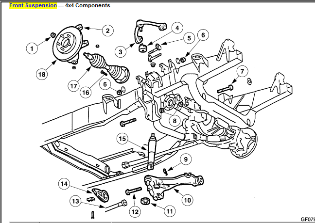
Alright, let's dive into the 2001 Ford F-150's front suspension diagram. Whether you're tackling a repair, planning a modification, or just trying to understand how your truck handles, knowing the ins and outs of this system is crucial. This article will break down the diagram, explain its components, and give you a solid understanding of how it all works together. We're aiming for a deep dive, but in a way that's clear and practical, even if you're not a seasoned mechanic.
Why This Diagram Matters
The front suspension diagram is your roadmap to understanding and working on your F-150's front end. It's essential for:
- Repairing Worn Parts: Identifying and replacing worn ball joints, tie rod ends, or control arm bushings.
- Troubleshooting Handling Issues: Diagnosing problems like excessive bouncing, steering wheel shake, or uneven tire wear.
- Performing Upgrades: Planning and executing modifications such as lift kits or performance shocks.
- General Maintenance: Understanding the lubrication points and inspection areas to keep everything running smoothly.
Without a clear understanding of the suspension layout, you're essentially working in the dark. This diagram illuminates the path to successful repairs and modifications.
Key Specs and Main Parts of the 2001 F-150 Front Suspension
The 2001 F-150 utilizes a double wishbone (or double A-arm) independent front suspension. Let's break down the key components:
- Upper and Lower Control Arms: These are the primary structural components. The upper control arm connects the upper portion of the spindle to the frame, while the lower control arm connects the lower portion of the spindle to the frame. They allow the wheel to move up and down while maintaining proper camber.
- Spindle (or Steering Knuckle): This component houses the wheel hub, bearings, and brake rotor. It pivots to allow steering. The terms spindle and steering knuckle are often used interchangeably.
- Coil Spring: Located between the lower control arm and the frame, the coil spring absorbs bumps and supports the weight of the vehicle.
- Shock Absorber (Damper): Mounted inside the coil spring or alongside it, the shock absorber dampens the oscillations of the spring, preventing excessive bouncing and controlling body roll.
- Ball Joints: These are spherical bearings that connect the control arms to the spindle. They allow the spindle to pivot for steering and move up and down with the suspension. There are typically upper ball joints and lower ball joints.
- Tie Rod Ends: These connect the steering rack to the spindles. They transmit steering input from the steering wheel to the wheels. The tie rod assembly includes an inner tie rod end, the tie rod itself, and the outer tie rod end.
- Stabilizer Bar (Sway Bar): This torsion bar connects the left and right sides of the suspension. It reduces body roll during cornering by transferring force from one side of the suspension to the other.
- Wheel Hub and Bearings: The wheel hub provides a mounting point for the wheel and rotor. The wheel bearings allow the wheel to rotate smoothly.
Understanding the Symbols on the Diagram
A typical suspension diagram uses a standardized set of symbols to represent components and connections. Here's a breakdown:
- Solid Lines: Represent rigid components like control arms, tie rods, and the frame. Their thickness might indicate the component's relative size or load-bearing capacity.
- Dashed Lines: Often indicate hidden components, lines of force, or reference points.
- Circles/Spheres: Usually represent joints like ball joints or bushings, indicating a pivot point.
- Spring Symbols (Coiled Lines): Represent the coil springs. The number of coils and the spacing might be stylized, but the symbol always represents a spring.
- Shock Absorber Symbol (Cylinder with Piston Rod): Represents the shock absorber.
- Arrows: Indicate the direction of movement or force. For example, an arrow might show the direction of wheel travel or the force applied by a spring.
- Torque Specifications: Often included near bolt locations, these indicate the correct torque value (e.g., "85 ft-lbs"). Always use a torque wrench and adhere to these specifications!
- Lubrication Points: Sometimes marked with a grease gun symbol, these indicate where to apply grease.
Pay close attention to the legend or key on the diagram. This will typically explain any unique symbols or color coding used.
How It Works: The Suspension in Action
The 2001 F-150's double wishbone suspension is designed to provide a balance of ride comfort and handling. Here's a simplified explanation of how it functions:
- Bump Absorption: When the wheel encounters a bump, it moves upwards. This compresses the coil spring, which absorbs the energy of the impact.
- Dampening Oscillation: As the spring compresses and rebounds, the shock absorber dampens the oscillations, preventing the wheel from bouncing excessively.
- Steering: When you turn the steering wheel, the steering rack pushes or pulls on the tie rods. This movement is transferred to the spindles, causing the wheels to pivot and change direction.
- Body Roll Control: During cornering, the stabilizer bar resists body roll. When one wheel moves upwards, the stabilizer bar twists and transfers some of that force to the opposite wheel, helping to keep the vehicle level.
Real-World Use: Basic Troubleshooting Tips
Let's say you're experiencing some common front suspension issues. Here's how the diagram can help:
- Clunking Noise: A clunking noise when going over bumps could indicate worn ball joints, tie rod ends, or control arm bushings. Use the diagram to locate these components and visually inspect them for play or damage.
- Steering Wheel Shake: Steering wheel shake can be caused by worn tie rod ends or unbalanced tires. Check the tie rod ends for excessive play.
- Uneven Tire Wear: Uneven tire wear can be a sign of misaligned suspension components, such as a bent control arm or worn ball joints. The diagram will show the relative positions of these parts, helping you identify potential problems.
- Excessive Bouncing: Excessive bouncing indicates worn shock absorbers. The diagram shows their location, making it easy to identify and replace them.
Safety First! Risky Components
Working on the front suspension can be dangerous due to the stored energy in the coil springs. Here are some key safety considerations:
- Spring Compression: NEVER disassemble the suspension without properly compressing the coil spring using a spring compressor. These springs are under immense pressure and can cause serious injury or death if released suddenly.
- Vehicle Support: Always use jack stands to support the vehicle before working on the suspension. Never rely solely on a jack.
- Brake Lines: Be extremely careful when working near brake lines. Damaging a brake line can result in loss of braking power.
- Torque Specifications: Always use a torque wrench and adhere to the specified torque values for all bolts and fasteners. Over-tightening can damage components, while under-tightening can lead to failure.
Remember: If you're not comfortable performing a particular repair, it's always best to consult a qualified mechanic. Your safety, and the safety of others, is paramount.
Now you've got a solid understanding of the 2001 Ford F-150 front suspension diagram. It’s a valuable tool for understanding your truck's workings and tackling repairs. Good luck!
We have the complete 2001 Ford F-150 front suspension diagram available for download. Contact us for the file.