2001 Ford F150 Radio Wiring Harness Diagram
The 2001 Ford F150, a workhorse for many, is getting on in years. A common issue many owners face revolves around the audio system. Whether you're upgrading to a modern head unit, diagnosing a faulty speaker, or just trying to understand how the whole thing works, understanding the radio wiring harness is absolutely crucial. This article serves as a comprehensive guide to the 2001 Ford F150 radio wiring harness diagram, empowering you to tackle audio-related projects with confidence. We'll cover its purpose, key components, wire identification, how the system operates, troubleshooting tips, and critical safety precautions. Having this knowledge will not only save you money on mechanic fees but also unlock a deeper understanding of your truck's electrical system.
Purpose of Understanding the Radio Wiring Harness
Why bother learning about the radio wiring harness? The reasons are numerous:
- Aftermarket Head Unit Installation: Replacing the factory radio with a new one is a common upgrade. Understanding the harness allows you to properly connect the new unit without cutting and splicing wires haphazardly. This ensures proper functionality and prevents potential electrical issues.
- Speaker Upgrades: Upgrading speakers often involves tapping into the existing speaker wires. Knowing the harness layout ensures you connect the new speakers to the correct outputs.
- Troubleshooting Audio Problems: Is one of your speakers not working? Is there a persistent buzzing sound? Understanding the wiring diagram is the first step in diagnosing the source of the problem.
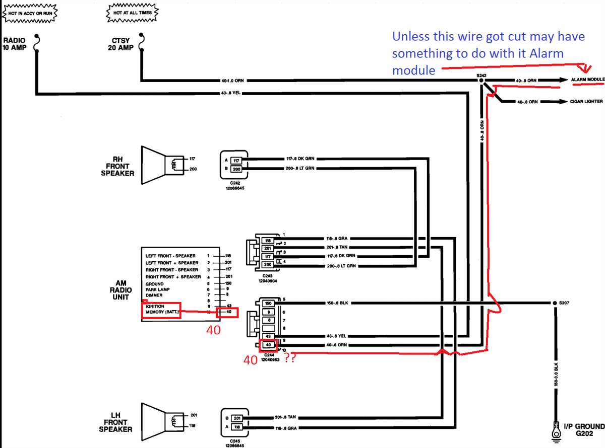
- Alarm System Integration: Some alarm systems integrate with the radio to mute the audio during an alarm event. The wiring diagram will help you identify the necessary wires for this integration.
- Educational Purposes: Gaining a working knowledge of automotive electrical systems is invaluable for any DIY mechanic. The radio wiring harness is a relatively simple circuit to learn from.
Key Specs and Main Parts
The 2001 Ford F150 radio wiring harness generally adheres to the standard Ford wiring color codes of the era. It's a 16-pin connector, although not all pins are necessarily populated, depending on the specific trim level and options package of your truck. It's important to note that the exact wiring might vary slightly depending on whether you have a standard cab, extended cab, or crew cab, and whether you have the base audio system or the premium sound system (which typically included an amplifier).
Here's a general overview of the main wires and their functions:
- 12V Constant (Battery): This wire provides constant power to the radio, even when the ignition is off. This is used for memory retention (presets, clock, etc.). Typically a Yellow wire.
- 12V Switched (Ignition): This wire provides power only when the ignition is turned on. This turns the radio on and off with the vehicle. Typically a Red wire.
- Ground: Provides the return path for the electrical current. Typically a Black wire.
- Illumination: This wire dims the radio's display when the headlights are turned on. Typically a Light Blue/Red stripe wire.
- Power Antenna: This wire provides power to the power antenna (if equipped) when the radio is turned on. Typically a Pink wire.
- Remote Turn-On (Amplifier): If your truck has a factory amplifier, this wire turns the amplifier on and off with the radio. Typically a Dark Blue/White stripe wire.
- Speaker Wires (Front Left, Front Right, Rear Left, Rear Right): These wires carry the audio signal to the speakers. Each speaker has a positive (+) and negative (-) wire. The color codes for these wires are specific to each speaker location and typically involve a solid color for the positive and a stripe of the same color for the negative.
- Front Left: White/Light Green (-) and White/Pink (+)
- Front Right: Gray/Light Blue (-) and Gray/White (+)
- Rear Left: Tan/Black (-) and Orange/Light Green (+)
- Rear Right: Dark Blue/White (-) and Red/Light Green (+)
Key Specs:
- Connector Type: 16-Pin (Modified ISO standard)
- Voltage: 12V DC
- Wire Gauge: Typically 18-22 AWG (American Wire Gauge)
Symbols - Understanding the Wiring Diagram
The wiring diagram uses standardized symbols to represent electrical components and connections. Here's a breakdown of common symbols:
- Solid Lines: Represent wires. The thickness of the line may indicate wire gauge, though this is not always consistent.
- Dashed Lines: May represent a shielded wire or a connection to a ground point.
- Circles: Often represent connectors or junctions where multiple wires are joined.
- Squares/Rectangles: Represent electrical components, like the radio head unit or an amplifier.
- Ground Symbol: Looks like an upside-down Christmas tree. Indicates a connection to the vehicle's chassis ground.
- Color Codes: Each wire is identified by a color code. The diagram will have a legend that explains what each color represents (e.g., "BK" for Black, "RD" for Red, "WH" for White, etc.). Wires with stripes will be designated by two color codes separated by a forward slash (e.g., "WH/BK" for White with a Black stripe).
Understanding these symbols is crucial for accurately interpreting the wiring diagram.
How It Works
The radio wiring harness is essentially the central nervous system of the audio system. It provides the power, ground, and speaker connections that allow the radio to function. The 12V constant wire keeps the radio's memory alive, while the 12V switched wire actually turns the radio on and off. The ground wire completes the circuit. The illumination wire dims the display to prevent glare at night.
The radio then amplifies the audio signal and sends it to the speakers through the speaker wires. Each speaker has a dedicated pair of wires, one positive and one negative. The polarity (positive and negative) of the speaker wires is important. Reversing the polarity can cause the speakers to sound thin or out of phase.
If the truck has a factory amplifier, the radio sends a low-level audio signal to the amplifier, which then amplifies the signal further before sending it to the speakers. The remote turn-on wire tells the amplifier to turn on only when the radio is on.
This entire system relies on a clean and stable power supply, proper grounding, and correctly wired connections. Problems in any of these areas can lead to audio issues.
Real-World Use - Basic Troubleshooting Tips
Here are a few basic troubleshooting tips using the radio wiring diagram:
- Radio Not Turning On: Check the 12V constant and 12V switched wires with a multimeter. Make sure they are receiving power. Also, check the ground wire for continuity to the vehicle's chassis. If the fuses associated with the radio are blown, replace them with the proper amperage fuse.
- No Sound From Speakers: Check the speaker wires for continuity. Make sure the speakers are properly connected and not blown. You can test a speaker by connecting it briefly to a 1.5V battery; you should hear a faint pop.
- Buzzing or Hissing Sounds: Check the ground wire for a good connection. Loose ground connections are a common cause of noise. Also, check the RCA cables (if applicable) for damage.
- Dim or Flickering Display: Check the illumination wire. Ensure it is properly connected and receiving a signal when the headlights are turned on.
- Speaker Only Playing Quietly: Check for shorts in the speaker wire, particularly at the speaker terminal. A short can cause the amplifier output to be reduced for that channel.
Remember to always disconnect the negative battery terminal before working on any electrical components in your vehicle.
Safety - Highlight Risky Components
Working with automotive electrical systems can be dangerous. Here are some key safety precautions:
- Disconnect the Battery: Always disconnect the negative battery terminal before working on any electrical components. This prevents accidental shorts and electrical shocks.
- Use a Multimeter: A multimeter is an essential tool for diagnosing electrical problems. Learn how to use it safely and accurately.
- Avoid Working With Live Wires: Never work on live wires. If you need to test a wire, use a multimeter to check for voltage first.
- Fuse Protection: Ensure that all circuits are properly fused. Using the correct amperage fuse is crucial to prevent damage to the wiring and components. Replacing a blown fuse with a higher amperage fuse can cause a fire.
- Airbag System: Be extremely careful when working near the airbag system. Improper handling can cause the airbags to deploy, resulting in serious injury. If you are not comfortable working near the airbags, consult a professional.
- Consult a Professional: If you are unsure about any aspect of the repair, consult a qualified automotive electrician.
Specifically regarding the radio system, ensure you don't overload the circuit with a high-powered aftermarket amplifier. Exceeding the factory wiring's current capacity can lead to overheating and fire.
Now you are equipped with fundamental understanding about the wiring of your 2001 Ford F150 radio. Download the full wiring diagram to get started.