2001 Ford F350 Fuse Box Diagram Under Dash
Let's dive into the under-dash fuse box diagram for your 2001 Ford F350. Understanding this diagram is crucial for a number of reasons, from basic troubleshooting and repairs to installing aftermarket accessories. Consider this your roadmap to the electrical heart of your truck. This isn't just a random piece of paper; it's your key to quickly diagnosing electrical problems and preventing costly trips to the mechanic.
Purpose: Your Electrical Troubleshooting Guide
The fuse box diagram serves several vital purposes:
- Repair Identification: It allows you to quickly identify which fuse controls a specific circuit (e.g., headlights, radio, power windows). When a component fails, checking the corresponding fuse is the first step.
- Accessory Installation: If you're adding accessories like a new stereo system, auxiliary lights, or a trailer brake controller, the diagram helps you locate appropriate power sources and fuse them correctly, preventing overloads and potential fires.
- Preventing Electrical Fires: Incorrectly sized or blown fuses indicate potential circuit overloads or shorts. Addressing these issues promptly can prevent serious damage and even electrical fires.
- Understanding Your Vehicle's Electrical System: Beyond repairs, the diagram provides a fundamental understanding of how different components are interconnected within your F350's electrical system.
Key Specs and Main Parts of the Fuse Box
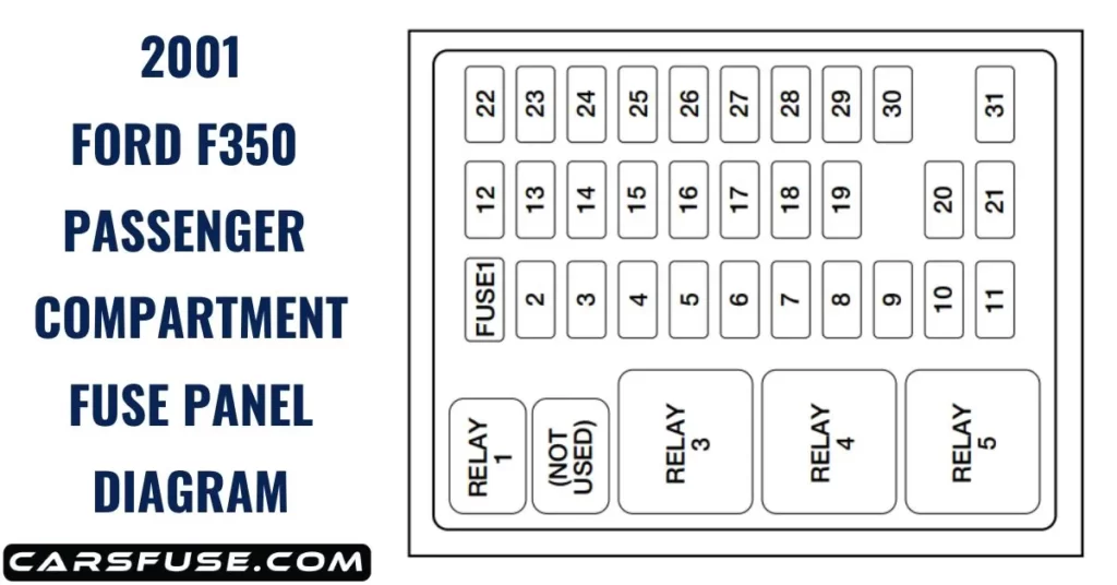
The under-dash fuse box in your 2001 F350 is typically located on the driver's side, usually beneath the dashboard and to the left of the steering column. You might need to remove a small access panel to expose it. The fuse box itself contains:
- Fuses: These are the sacrificial links that protect individual circuits. They're designed to blow (open) if the current exceeds a safe level, preventing damage to wiring and components. Fuses are rated in Amperes (Amps), which indicates the maximum current they can handle.
- Relays: Relays are electromechanical switches that allow a low-current circuit to control a high-current circuit. For example, the headlight relay allows a small switch on the dashboard to control the high-current headlights. Relays consist of a coil, which when energized creates a magnetic field, and a set of contacts that open or close.
- Fuse Puller: Often integrated into the fuse box cover, a fuse puller is a small plastic tool used to safely remove and install fuses. This tool is *essential* for preventing damage to the fuse box terminals.
- Terminals: These are the metal connectors that the fuses and relays plug into. It's important these are clean and free of corrosion.
- Wiring Harness Connectors: These connectors tie into the fuse box itself, these are usually multi-pin connectors that bring many circuits into the fuse panel all at once.
The specific Amp ratings of the fuses are *critical*. Always replace a blown fuse with one of the *same* Amp rating. Using a higher-rated fuse can allow excessive current to flow, potentially damaging components or causing a fire. The fuse box cover should have a label detailing which fuse controls which circuit.
Decoding the Symbols: Lines, Colors, and Icons
Fuse box diagrams use a standardized set of symbols to represent different components and connections. Here's a breakdown:
- Lines: Solid lines represent wires, indicating the electrical connections between components. Dashed lines may represent ground connections.
- Colors: Wire colors are often indicated on the diagram. Common colors include red (power), black (ground), and various other colors to identify specific circuits. Knowing the wire color can be especially useful when tracing a circuit.
- Icons:
- A small rectangle with a line through it often represents a fuse. The Amp rating is usually written next to the rectangle.
- A square with a coil symbol inside usually represents a relay.
- A circle with a ground symbol represents a ground connection.
- Simplified icons of components (e.g., headlight, horn) may be used to indicate the circuits they control.
- Numbering and Labeling: Each fuse and relay position is typically numbered or labeled, corresponding to the legend on the fuse box cover or in the owner's manual.
Pay close attention to the legend that accompanies the diagram. This legend is the *key* to understanding which fuse or relay controls which component. Without the legend, the diagram is essentially useless.
How It Works: A Simplified Electrical Flow
Imagine your F350's electrical system as a network of pathways. The battery provides the power source, and the wiring acts as the roads that carry electricity to various components. The fuse box acts as a central distribution point, with each fuse protecting a specific "road."
When you turn on a switch (e.g., headlights), you complete a circuit, allowing current to flow from the battery, through the fuse, through the switch, and to the component (headlights). If there's a short circuit (e.g., a wire is damaged and touches the vehicle's metal frame), the current surges, and the fuse blows, interrupting the circuit and preventing further damage.
Relays are used to control circuits that require high current. The low-current control circuit energizes the relay coil, which then closes the contacts of the high-current circuit, powering the component.
Real-World Use: Basic Troubleshooting Tips
Here's how you can use the fuse box diagram to troubleshoot common electrical problems:
- Component Failure: If a component (e.g., cigarette lighter) stops working, consult the diagram to identify the corresponding fuse. Check the fuse for continuity using a multimeter. If the fuse is blown, replace it with a fuse of the *same* Amp rating. If the new fuse blows immediately, there's likely a short circuit in the wiring or the component itself.
- Intermittent Problems: Intermittent electrical problems can be tricky to diagnose. The fuse box diagram can help you narrow down the possible causes by identifying circuits that share a common fuse or relay.
- Accessory Installation: When installing accessories, use the diagram to identify an appropriate power source. Always use a fuse tap or add-a-circuit to tap into an existing circuit, and ensure the new circuit is properly fused. Never overload an existing circuit.
For example, let's say your F350's radio suddenly stops working. First, locate the fuse box diagram. Find the fuse labeled "Radio" or "Audio System." Use the fuse puller to remove the fuse and inspect it. If the fuse is blown (the filament inside is broken), replace it with a fuse of the same Amp rating. If the radio still doesn't work, there may be a problem with the radio itself, the wiring, or the ground connection.
Safety First: Handling Risky Components
Working with electrical systems can be dangerous. Here are some important safety precautions:
- Disconnect the Battery: Before working on the fuse box or any electrical component, disconnect the negative battery cable to prevent accidental short circuits and electric shock.
- Use Insulated Tools: Use tools with insulated handles to prevent electric shock.
- Never Bypass a Fuse: Never bypass a fuse by using a wire or a higher-rated fuse. This can overload the circuit and cause a fire.
- Be Careful with Relays: Relays can sometimes get hot, especially if they are malfunctioning. Be cautious when handling them.
- Don't Work in Wet Conditions: Never work on electrical systems in wet or damp conditions.
High-current circuits, such as those for the starter motor or alternator, can deliver a *lethal* electric shock. Exercise extreme caution when working with these circuits. If you're not comfortable working with electrical systems, consult a qualified mechanic.
We have the complete 2001 Ford F350 Under-Dash Fuse Box Diagram file available for download. It includes a detailed map of all fuses and relays, along with their corresponding functions and Amp ratings. This will be invaluable for your troubleshooting and repair endeavors. Be sure to use the correct diagram that matches your specific vehicle year and trim level, as there can be subtle variations.