2001 Gmc Sierra Radio Wiring Diagram
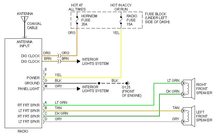
Alright, let's dive into the 2001 GMC Sierra radio wiring diagram. This is a crucial document if you're planning any audio modifications, repairs, or even just trying to understand how the factory system functions. Forget haphazardly cutting wires and hoping for the best – this diagram is your roadmap to success.
Purpose of the Wiring Diagram
Why bother with a wiring diagram? Simple: it prevents costly mistakes and streamlines your work. It's invaluable for:
- Radio Replacement: Installing an aftermarket head unit requires understanding the factory wiring to connect power, ground, speakers, and other essential signals.
- Troubleshooting Audio Problems: If your radio isn't working, the diagram helps you trace the signal path and identify the faulty component (e.g., a blown fuse, a broken wire, or a failing amplifier).
- Adding Aftermarket Amplifiers or Speakers: Tapping into the existing wiring for additional audio components demands knowing which wires carry which signals to avoid damage to your equipment or the vehicle's electrical system.
- Understanding the Vehicle's Electrical System: The radio circuit is connected to other systems (like the ignition and lighting). Studying the diagram provides insights into the broader electrical architecture of your 2001 Sierra.
Key Specs and Main Parts
The 2001 GMC Sierra's audio system, depending on the trim level and options, can vary in complexity. However, the core components and wiring principles remain the same. Here's what you'll typically find:
- Head Unit: The radio itself. This contains the receiver, amplifier, and controls. It connects to power, ground, antenna, and speakers.
- Speakers: Located in the doors, dashboard, and sometimes the rear deck. Each speaker has a positive (+) and negative (-) wire.
- Wiring Harness: The connector that plugs into the back of the head unit. This harness contains all the necessary wires for power, ground, speakers, and other functions.
- Antenna: Receives radio signals. It connects to the head unit via an antenna cable.
- Amplifier (Optional): Some Sierras came with a separate amplifier, usually located under the center console or behind the rear seat. This amplifier boosts the audio signal before it's sent to the speakers.
- OnStar Module (Optional): If equipped, the OnStar system integrates with the audio system for hands-free calling and other services. This will have its own set of wiring and connections.
- Chimes Module: The chimes module is responsible for producing warning chimes. It typically sends the chime audio signal through the front speakers, and the diagram will show this integration.
Decoding the Symbols
A wiring diagram is useless if you can't decipher its symbols. Here's a breakdown of the common symbols you'll encounter in the 2001 GMC Sierra radio wiring diagram:
- Solid Lines: Represent wires. The thickness of the line doesn't necessarily indicate wire gauge.
- Dashed Lines: Often indicate shielding or grounds.
- Color Codes: Wires are identified by color codes (e.g., RED, BLU, GRN, YEL). These codes are crucial for identifying the correct wires. Always double-check the color code against the actual wire in your vehicle.
- Circles: Represent connections or splices.
- Rectangles: Represent components like the head unit, speakers, amplifier, and fuses.
- Ground Symbol: Looks like an upside-down Christmas tree. Indicates a connection to the vehicle's chassis ground.
- Fuse Symbol: A squiggly line within a rectangle. Indicates a fuse in the circuit. The diagram should specify the fuse amperage.
- Connector Symbol: Usually a series of lines representing the pins in the connector. Each pin is typically numbered or labeled.
Example: You might see a solid red line labeled "RED/WHT" connected to a rectangle representing the head unit. This indicates a red wire with a white stripe that carries power to the head unit.
How It Works: The Signal Path
Understanding the signal path helps you troubleshoot problems and plan modifications. Here's a simplified overview:
- Power: The head unit receives power from the battery through a fuse and the ignition switch. When the ignition is turned on, power is supplied to the head unit.
- Ground: The head unit is grounded to the vehicle's chassis. A good ground connection is essential for proper operation.
- Antenna: The antenna receives radio signals and sends them to the head unit.
- Audio Signal Processing: The head unit processes the audio signal (e.g., AM/FM radio, CD player) and amplifies it.
- Speaker Output: The amplified audio signal is sent to the speakers through the speaker wires. Each speaker receives a separate signal for the left and right channels (and potentially front and rear).
- Amplifier (if equipped): If the vehicle has a separate amplifier, the head unit sends a low-level signal to the amplifier, which then boosts the signal and sends it to the speakers.
Real-World Use: Basic Troubleshooting
Let's say your radio isn't turning on. Here's how you can use the wiring diagram to troubleshoot the problem:
- Check the Fuse: Locate the fuse for the radio in the fuse box (the diagram will show its location). Use a multimeter to test the fuse for continuity. If the fuse is blown, replace it with a fuse of the same amperage.
- Verify Power and Ground: Use a multimeter to check for power and ground at the head unit's wiring harness. If you don't have power or ground, trace the wiring back to the fuse box or chassis ground to identify the break.
- Check the Wiring Harness: Inspect the wiring harness for loose connections, corroded terminals, or damaged wires.
- Isolate the Problem: If you suspect a faulty head unit, try connecting a known-good head unit to the wiring harness to see if it works.
Safety First!
Working with automotive electrical systems can be dangerous. Take these precautions:
- Disconnect the Battery: Always disconnect the negative terminal of the battery before working on any electrical components. This prevents accidental shorts and electrical shocks.
- Use a Multimeter Safely: Understand how to use a multimeter correctly and safely. Avoid touching exposed wires while taking measurements.
- Identify Potentially Risky Components: Capacitors can store electrical charge even after the battery is disconnected. Be careful when working around capacitors in the head unit or amplifier.
- Work in a Well-Lit Area: Good lighting is essential for seeing what you're doing and avoiding mistakes.
- If Unsure, Seek Professional Help: If you're not comfortable working with automotive electrical systems, consult a qualified mechanic or audio installer.
Important Note: Always double-check the wiring diagram against the actual wiring in your vehicle. Wiring configurations can vary depending on the trim level, options, and year of manufacture.
We have the complete 2001 GMC Sierra radio wiring diagram available for download. This detailed diagram will provide you with the specific wiring information you need for your vehicle. With this resource and a bit of patience, you'll be well-equipped to tackle your audio projects.