2001 Silverado Trailer Wiring Harness Diagram
Understanding the trailer wiring harness on your 2001 Silverado is crucial for safe and reliable towing. This article serves as a guide to the wiring diagram, enabling you to perform repairs, upgrades, or simply learn more about your truck's electrical system. We’ll break down the diagram, its components, and how to troubleshoot common issues. We even have the complete diagram available for you to download!
Purpose of the 2001 Silverado Trailer Wiring Harness Diagram
The wiring diagram is essentially a roadmap of the electrical circuits dedicated to trailer connections. It's not just a pretty picture; it's an essential tool for several reasons:
- Repairing Damaged Wiring: Accidents happen. Wires get cut, corroded, or frayed. The diagram allows you to identify the damaged wire and its function, enabling precise repair.
- Adding or Modifying Trailer Connectors: Perhaps you want to upgrade from a 4-pin to a 7-pin connector for brake control and auxiliary power. The diagram shows you where to tap into the existing system.
- Troubleshooting Electrical Problems: Trailer lights not working? Brakes not engaging? The diagram helps isolate the problem by showing you the circuit path.
- Understanding the System: Even if you don't plan on performing any work, understanding the diagram gives you a better overall understanding of your truck's electrical system and how it interacts with your trailer.
Key Specs and Main Parts
The 2001 Silverado typically uses a standard trailer wiring system, and the diagram will highlight the following key components and specifications. Keep in mind that variations may exist based on trim level and factory options.
- Connector Type: Most 2001 Silverados came with a 7-way blade style connector, also known as an RV-style connector. Some models may have had a 4-way flat connector or provisions for both.
- Wire Gauge: Wire gauge is important for handling amperage. Generally, heavier gauge wires (lower numbers) are used for higher current circuits like trailer brakes and battery charging. Expect to see wires ranging from 10-gauge to 18-gauge. The diagram specifies the correct gauge for each circuit.
- Fuses and Relays: The trailer wiring is protected by fuses and sometimes relays located in the under-hood fuse box. The diagram shows the location of these fuses/relays and their amperage ratings.
- Grounding Point: A solid ground connection is critical for proper operation. The diagram will indicate the location of the grounding point for the trailer wiring harness, typically on the frame.
The main parts depicted in the diagram include:
- Trailer Connector: The physical connector at the rear of the truck where the trailer wiring plugs in.
- Wiring Harness: The bundle of wires connecting the trailer connector to the truck's electrical system.
- Fuses/Relays: Protective devices for the trailer circuits.
- Ground Connection: The point where the trailer wiring connects to the truck's chassis for a ground.
- Connections to Truck Systems: This includes connections to the brake light circuit, turn signal circuits, running light circuit, and battery (for battery charging or auxiliary power).
Understanding Wiring Diagram Symbols
A wiring diagram uses standard symbols to represent electrical components and connections. Learning to read these symbols is essential for understanding the diagram. Common symbols include:
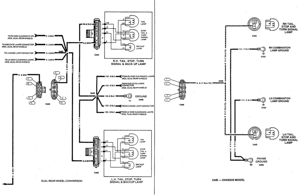
- Lines: Represent wires. Solid lines typically indicate standard wiring, while dashed lines may indicate optional or accessory wiring.
- Colors: Each wire is color-coded. The diagram includes a color code chart (e.g., BRN for Brown, YEL for Yellow, GRN for Green). These color codes are critical for identifying the correct wire.
- Circles with Numbers: Indicate connector pins. The number within the circle corresponds to the pin number on the trailer connector.
- Rectangles: Represent components like fuses, relays, or connectors.
- Ground Symbol: Usually looks like three horizontal lines decreasing in size, indicating a connection to ground.
- Splice Symbols: Indicate where two or more wires are joined together.
It's important to note that the diagram might use different line styles to represent wire gauge. A thicker line could mean a wire with a larger diameter (lower gauge number) capable of carrying more current.
How It Works: A Simplified Explanation
The trailer wiring harness essentially "taps" into the truck's existing lighting and braking systems. When you activate a function in the truck (e.g., turn signal, brake pedal), a signal is sent through the truck's wiring to the trailer wiring harness, which then transmits that signal to the corresponding lights or brakes on the trailer.
For example, when you press the brake pedal, the brake light switch sends power to the truck's brake lights. At the same time, a signal is sent through a dedicated wire in the trailer wiring harness to activate the trailer's brake lights. The same principle applies to turn signals and running lights.
A 7-way connector allows for additional functions like trailer brakes (controlled by a separate brake controller in the truck) and auxiliary power (used for charging a trailer battery or powering accessories within the trailer). The diagram details how these functions are wired and connected.
The brake controller is wired into the system, providing a proportional voltage to the trailer brakes depending on how hard the truck's brakes are applied. This ensures smooth and controlled braking while towing.
Real-World Use: Basic Troubleshooting Tips
Here are some common trailer wiring problems and how the diagram can help:
- No Trailer Lights: Check the fuses in the under-hood fuse box related to trailer lighting. The diagram shows you which fuses to check. If a fuse is blown, replace it with one of the correct amperage. If the fuse blows again immediately, there's likely a short circuit in the wiring.
- One Trailer Light Not Working: Use the diagram to trace the wiring for that specific light. Check for loose connections, corroded terminals, or damaged wires. Use a multimeter to test for voltage at the connector and along the wire path.
- Trailer Brakes Not Working: Ensure the brake controller is properly connected and functioning. Check the wiring between the brake controller and the trailer connector using the diagram. Verify the brake controller fuse is not blown.
- Weak or Flickering Lights: This often indicates a poor ground connection. Check the ground connection for the trailer wiring harness on the truck's frame. Clean and tighten the connection if necessary. Also, check the trailer's ground connection.
A multimeter is an invaluable tool for troubleshooting electrical problems. It allows you to measure voltage, current, and resistance, helping you pinpoint the source of the issue. Using the diagram in conjunction with a multimeter allows you to systematically test the circuit and identify any faults.
Safety: Handling Risky Components
Working with electrical systems can be dangerous. Always disconnect the negative battery cable before working on the trailer wiring harness to prevent accidental shorts or electrical shocks.
Fuses are designed to protect circuits from overloads. Never replace a fuse with one of a higher amperage rating, as this could damage the wiring and potentially cause a fire.
When working with wiring, use proper crimping tools and connectors to ensure secure and reliable connections. Poor connections can cause overheating and electrical failures.
Always double-check your work before reconnecting the battery. Ensure that all connections are secure and that there are no exposed wires or damaged components.
Brake controllers should be installed according to the manufacturer's instructions. Incorrect installation can lead to improper braking and potentially dangerous situations.
Working on a vehicle's electrical system requires caution and a good understanding of basic electrical principles. If you are not comfortable working with electricity, it's best to consult a qualified mechanic.
Ready to get started? We have the complete 2001 Silverado trailer wiring harness diagram ready for you. You can download it [LINK TO DOWNLOAD HERE - Replace with actual download link]. With the diagram in hand and the knowledge you've gained here, you'll be well-equipped to tackle your trailer wiring projects with confidence!