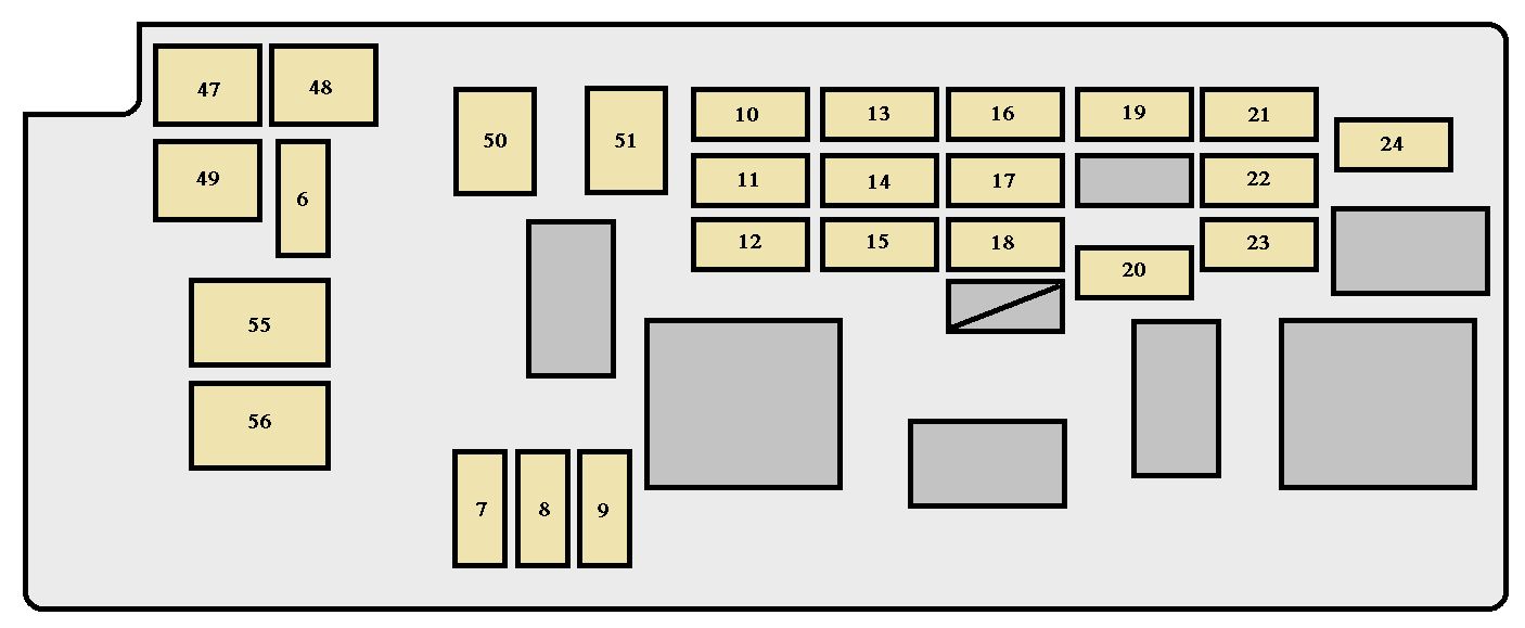
2001 Toyota Sequoia Fuse Box Diagram
The 2001 Toyota Sequoia, a full-size SUV, is known for its reliability, but like any vehicle, electrical issues can arise. Understanding the fuse box diagram is crucial for diagnosing and resolving these problems. This article will guide you through the intricacies of the 2001 Sequoia's fuse box, empowering you to tackle electrical repairs and modifications with confidence.
Purpose of the Fuse Box Diagram
The fuse box diagram serves as a roadmap to your Sequoia's electrical system. It identifies the location and function of each fuse and relay. Why is this important? Well, consider these scenarios:
- Troubleshooting electrical problems: A faulty circuit can manifest in various ways – a non-functioning headlight, a dead radio, or even a malfunctioning engine component. The fuse box diagram allows you to quickly identify the fuse protecting that circuit. If the fuse is blown, it points to a potential short circuit or overload in that system.
- Performing modifications: When adding aftermarket accessories like auxiliary lights, a new sound system, or a trailer brake controller, you need to tap into the vehicle's electrical system safely. The fuse box diagram helps you identify suitable power sources and protect your new additions with appropriate fuses.
- General maintenance and learning: Understanding your vehicle's electrical system can save you money on diagnostic fees and empower you to perform basic repairs yourself. The diagram provides a visual representation of how different components are wired together.
Key Specs and Main Parts
The 2001 Sequoia typically has two main fuse box locations:
- Interior Fuse Box: Located inside the cabin, usually under the dashboard on the driver's side. This box primarily houses fuses for interior accessories, lighting, and the instrument panel.
- Engine Compartment Fuse Box: Situated in the engine bay, this box contains fuses and relays for critical engine functions, exterior lighting, and the starting and charging systems.
Key components within each fuse box include:
- Fuses: These are safety devices designed to protect electrical circuits from overcurrent. They consist of a thin wire or strip that melts and breaks the circuit if the current exceeds a predetermined level. Fuses are rated in amperes (amps), indicating the amount of current they can handle before blowing.
- Relays: Electromagnetic switches that control high-current circuits using a low-current signal. They are often used to switch headlights, starter motors, and other power-hungry components.
- Circuit Breakers: Reusable overcurrent protection devices. Unlike fuses, they don't need to be replaced; instead, they "trip" and can be reset after the fault is corrected. The 2001 Sequoia primarily relies on fuses, with fewer applications using circuit breakers.
Symbols – Understanding the Diagram's Language
Fuse box diagrams aren't just a collection of names; they employ specific symbols to convey information. Here's a breakdown of common symbols you'll encounter:
- Lines: Represent electrical wires. The thickness of the line generally doesn't indicate wire gauge in these diagrams, but rather its connectivity.
- Colors: Different colored wires are often indicated on the diagram. These colors correspond to the actual wire colors in the vehicle, helping you trace circuits. Common colors include red (power), black (ground), blue, yellow, green, and white.
- Icons: Represent specific components. For example:
- A headlight symbol indicates the headlight circuit fuse.
- A radio symbol indicates the radio fuse.
- A fan symbol indicates the cooling fan fuse or relay.
- Numbers followed by "A" (e.g., 10A, 20A) indicate the fuse amperage rating.
- Fuse Shape: While the shape of the fuse in the diagram may not exactly match the physical fuse (blade, cartridge, etc.), it identifies that the component is a fuse.
The legend accompanying the diagram is crucial. It translates these symbols and abbreviations into understandable functions. Always refer to the legend for accurate interpretation.
How It Works
The electrical system is designed with multiple circuits, each protected by a fuse. When a component draws excessive current (due to a short circuit, overload, or malfunction), the corresponding fuse blows. This interrupts the flow of electricity to that circuit, preventing damage to wiring and components. Relays act as electrically controlled switches, allowing a low-current signal from the ignition switch or a control module to activate a high-current circuit like the headlights or starter motor.
Think of it like this: the fuse is a weak link in a chain. If the chain experiences too much stress (overcurrent), the weak link (fuse) breaks to protect the rest of the chain (the wiring and components).
Real-World Use – Basic Troubleshooting Tips
Here's how to use the fuse box diagram for basic troubleshooting:
- Identify the Problem: Determine which component isn't working. For example, the left headlight is out.
- Consult the Diagram: Locate the fuse box diagram (usually inside the fuse box cover or in the owner's manual).
- Find the Fuse: Identify the fuse associated with the left headlight circuit. The diagram will show its location and amperage rating.
- Inspect the Fuse: Remove the fuse using a fuse puller (a small plastic tool designed for this purpose). Visually inspect the fuse. A blown fuse will have a broken filament inside.
- Test the Fuse: Even if the filament looks intact, use a multimeter to test the fuse for continuity. Set the multimeter to continuity mode (usually indicated by a diode symbol or a buzzer). Touch the probes to both ends of the fuse. If the multimeter beeps or shows a value close to zero, the fuse is good. If it shows infinite resistance or no beep, the fuse is blown.
- Replace the Fuse: Replace the blown fuse with a new fuse of the same amperage rating. Never use a fuse with a higher amperage rating, as this can damage the wiring and components.
- Test the Component: After replacing the fuse, test the component to see if it's working again. If the fuse blows again immediately, there's a persistent short circuit that needs further investigation.
Safety – Highlighting Risky Components
Working with automotive electrical systems involves inherent risks. Always take these precautions:
- Disconnect the Battery: Before working on any electrical components, disconnect the negative (-) terminal of the battery. This prevents accidental short circuits and electrical shocks.
- Use the Right Tools: Use insulated tools designed for automotive electrical work.
- Never Bypass a Fuse: Never bypass a fuse by wrapping it with foil or wire. This eliminates the overcurrent protection and can lead to a fire.
- Be Cautious Around the SRS (Airbag) System: The SRS system has its own fuses and wiring. Incorrectly disconnecting or tampering with this system can cause the airbags to deploy unexpectedly, resulting in serious injury. If you need to work near the SRS system, consult a qualified technician.
- High Current Components: Be extremely careful around the main fuses and relays in the engine compartment fuse box. These components handle high currents and can deliver a powerful shock.
Remember, if you are uncomfortable working on the electrical system or suspect a complex problem, it's best to consult a qualified automotive electrician.
We have a downloadable PDF file containing the 2001 Toyota Sequoia fuse box diagram. You can use it for your personal reference while working on your vehicle.