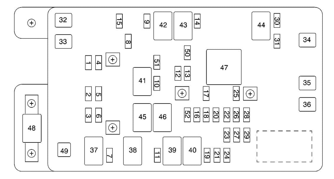
2002 Chevrolet Trailblazer Fuse Box Diagram
Alright, let's dive into the 2002 Chevrolet Trailblazer's fuse box diagram. Understanding this diagram is absolutely crucial for diagnosing electrical issues, performing modifications, or simply maintaining your Trailblazer. We're going to break it down in a way that's helpful for anyone with some experience under the hood.
Purpose: Your Trailblazer's Electrical Roadmap
Why bother with the fuse box diagram? Simple. It's your roadmap to the Trailblazer's electrical system. Think of it as a well-organized index of all the electrical components, their protection mechanisms (fuses and relays), and their locations. Without it, you're essentially troubleshooting in the dark, potentially causing more damage than you fix. Specifically, understanding the diagram allows you to:
- Diagnose Electrical Faults: Quickly identify which fuse protects a specific circuit, like the headlights, radio, or power windows.
- Perform Repairs: Pinpoint the faulty component and its associated wiring.
- Install Aftermarket Accessories: Safely tap into the electrical system for adding things like aftermarket lights, stereos, or alarms.
- Prevent Overloads: Ensure you're not exceeding the circuit's capacity when adding electrical accessories.
- General Maintenance: Keep a record of fuse replacements and monitor the health of your electrical system.
Key Specs and Main Parts
The 2002 Trailblazer, like most vehicles, has multiple fuse boxes. However, we'll primarily focus on the two most important ones:
- Underhood Fuse Box (Engine Compartment): This box houses fuses and relays for high-current components like the starter motor, alternator, fuel pump, cooling fan, and headlights. It typically has a hinged cover with the diagram printed on the inside.
- Rear Fuse Box (Rear Passenger Compartment): Located in the rear passenger compartment, this box typically handles circuits related to interior lighting, rear wipers, power seats, and the rear defroster.
Key parts you'll find within these boxes include:
- Fuses: These are the circuit protectors. They contain a thin metal filament that melts and breaks the circuit when the current exceeds the fuse's rating. They are rated in amperes (amps), indicating the maximum current they can handle. Common ratings include 5A, 10A, 15A, 20A, 25A, 30A, and 40A.
- Relays: Relays are electromechanical switches that use a small current to control a larger current. They're often used to switch on high-power devices like headlights, horns, and fuel pumps. They consist of a coil, contacts, and a spring. When the coil is energized, it pulls the contacts together, completing the circuit.
- Circuit Breakers: Circuit breakers are similar to fuses, but they can be reset. They trip when the current exceeds their rating, but instead of blowing, they open the circuit and can be manually reset after the overload is removed.
- Diodes: Diodes allow current to flow in only one direction, protecting sensitive components from reverse polarity.
Decoding the Symbols: A Visual Language
The fuse box diagram uses a set of symbols to represent different components and connections. Understanding these symbols is essential for interpreting the diagram correctly.
- Lines: Lines represent wires or electrical conductors. A solid line indicates a direct connection, while a dashed line might indicate a ground connection or a shielded wire. The thickness of the line doesn't usually indicate wire gauge on these diagrams.
- Colors: Wire colors are often indicated on the diagram using abbreviations (e.g., BLU for blue, RED for red, BLK for black). These colors help you trace wires in the vehicle.
- Fuse Symbols: Fuses are typically represented by a rectangle with a wavy line inside. The amperage rating is usually printed next to the symbol.
- Relay Symbols: Relays are usually represented by a coil symbol (a series of loops) and a switch symbol. The switch symbol indicates the contacts that are opened or closed when the relay is energized.
- Component Symbols: Various symbols represent different components, such as headlights, motors, sensors, and control modules. These symbols are usually standardized and can be found in automotive electrical reference materials.
Pay close attention to the legend or key on the diagram. It will explain any unique symbols or abbreviations used.
How It Works: From Battery to Component
The electrical system in your Trailblazer is a complex network of circuits. The battery provides the power source. From there, the power flows through the wiring harness, protected by fuses and controlled by relays. Here's a simplified overview:
- Power Source: The battery provides the initial voltage (12V in most automotive systems).
- Distribution: The power is distributed to various circuits through the wiring harness.
- Protection: Fuses and circuit breakers protect each circuit from overloads and short circuits. If the current exceeds the fuse's rating, the fuse blows, breaking the circuit and preventing damage.
- Control: Relays control the flow of current to high-power devices. The control signal for the relay comes from a switch or a control module.
- Load: The load is the device that consumes the electrical power, such as a light bulb, motor, or electronic module.
- Ground: The circuit is completed by returning the current to the battery through the ground connection.
Real-World Use: Troubleshooting Tips
Okay, let's get practical. Here's how you can use the fuse box diagram for troubleshooting:
- Identify the Problem: What's not working? Is it the headlights, the radio, or something else?
- Locate the Fuse: Consult the fuse box diagram to find the fuse that protects the circuit for the malfunctioning component.
- Inspect the Fuse: Remove the fuse and visually inspect it. If the filament is broken, the fuse is blown and needs to be replaced. You can also use a multimeter to check for continuity across the fuse. Set the multimeter to continuity mode (usually indicated by a sound wave symbol). If you hear a beep, the fuse is good. If not, it's blown.
- Replace the Fuse: Replace the blown fuse with a new fuse of the same amperage rating. Using a fuse with a higher amperage rating can damage the circuit.
- Test the Circuit: After replacing the fuse, test the circuit to see if the problem is resolved. If the fuse blows again immediately, there's likely a short circuit in the wiring or the component itself.
- Relay Check: If replacing the fuse doesn't solve the problem, the relay might be faulty. You can test the relay by swapping it with a known good relay or by using a multimeter to check for continuity and resistance.
Safety First: Respect the Electrical System
Working with automotive electrical systems can be dangerous if you're not careful. Here are some important safety precautions:
- Disconnect the Battery: Always disconnect the negative battery terminal before working on any electrical components. This prevents accidental shorts and electrical shocks.
- Use the Right Tools: Use insulated tools designed for automotive electrical work.
- Never Replace a Fuse with a Higher Amperage: This can overload the circuit and cause a fire.
- Avoid Working in Wet Conditions: Water can conduct electricity and create a shock hazard.
- Be Careful Around Airbags: Airbags are explosive devices and can be triggered accidentally if you're not careful. Consult a service manual for proper procedures before working near airbags. The circuits for airbags are often brightly colored (usually yellow) as a warning.
Components like the airbag system, anti-lock braking system (ABS), and engine control module (ECM) are particularly sensitive and can be damaged by improper handling. If you're not comfortable working on these systems, it's best to consult a qualified technician.
With the right diagram and a methodical approach, you can confidently diagnose and repair many electrical issues on your 2002 Chevrolet Trailblazer. Remember to always prioritize safety and double-check your work. Happy wrenching!
We have the full 2002 Chevrolet Trailblazer fuse box diagrams available for download. This resource provides a detailed visual guide to your vehicle's electrical system. It includes clear layouts of both the underhood and rear fuse boxes, along with a legend of symbols and abbreviations. Having this diagram on hand will significantly aid in troubleshooting electrical issues, performing repairs, and safely installing aftermarket accessories. It will be invaluable in maintaining and understanding your Trailblazer's electrical system. Get your copy now and take control of your vehicle's electrical maintenance!