
2002 Chevy Tahoe Stereo Wiring Harness
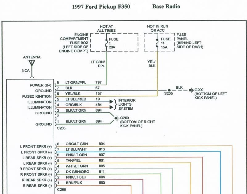
Understanding the 2002 Chevy Tahoe stereo wiring harness is crucial whether you're upgrading your factory system, troubleshooting audio issues, or simply trying to learn more about your vehicle's electrical system. This article provides a detailed breakdown of the harness, offering insights that will empower you to confidently tackle various DIY projects. We'll cover the purpose of the diagram, key specs, the meaning of different symbols, how the system works, real-world troubleshooting, and vital safety precautions. Finally, know that we have a downloadable wiring diagram available to assist you further.
Why Understand the 2002 Chevy Tahoe Stereo Wiring Harness?
The wiring harness is the backbone of your Tahoe's audio system. It serves as the central point for all electrical connections related to the stereo, speakers, and any aftermarket accessories you might install. Understanding this harness is essential for:
- Upgrading Your Stereo: Replacing the factory stereo often requires adapting the existing harness to your new unit. Knowing the function of each wire prevents damage and ensures a clean, professional installation.
- Speaker Replacement: Identifying speaker wires accurately prevents reversed polarity (which negatively impacts sound quality) and potential amplifier damage.
- Troubleshooting Audio Problems: When your audio system malfunctions – no sound, distorted sound, or intermittent operation – understanding the wiring harness helps you pinpoint the source of the problem.
- Installing Aftermarket Accessories: Adding amplifiers, subwoofers, or other audio enhancements requires tapping into the existing wiring harness safely and correctly.
- Learning Automotive Electrical Systems: Dissecting the wiring harness provides a practical, hands-on approach to understanding broader automotive electrical concepts.
Key Specs and Main Parts of the Harness
The 2002 Chevy Tahoe stereo wiring harness typically consists of two main connectors:
- Power/Speaker Connector: This connector handles the primary power supply (12V constant, 12V switched), ground, and speaker outputs. It's usually the larger of the two connectors.
- Data/Chime Connector: This connector carries data signals from the vehicle's computer system, allowing the stereo to communicate with other components like the OnStar system (if equipped) and the chime module (for turn signals, door ajar warnings, etc.). This connector is often smaller and contains fewer wires.
Key electrical specifications to be aware of include:
- Voltage: The system operates on a 12-volt DC (direct current) system. Always disconnect the negative battery terminal before working on the electrical system to prevent shorts and potential damage.
- Wire Gauge: Speaker wires are generally 16-18 gauge, while power and ground wires may be thicker (12-14 gauge) to handle higher current loads.
- Impedance: Factory speakers are typically 4 ohms. Matching the impedance of aftermarket speakers to the head unit's specifications is critical to prevent damage. Using speakers with a lower impedance than the head unit is designed for can overload the amplifier and cause it to overheat or fail.
- Fuse Rating: The radio circuit typically has a fuse rated between 10 and 20 amps. Check the fuse panel diagram for the exact rating. Never replace a blown fuse with one of a higher amperage, as this could create a fire hazard.
Understanding Wiring Diagram Symbols
A wiring diagram is essentially a roadmap of the electrical system. Here's a breakdown of common symbols:
- Lines: Solid lines represent wires. Dashed lines may represent shielded cables or connections through modules.
- Colors: Each wire is color-coded. Common colors include Red (power), Black (ground), Yellow (constant power), Blue (remote turn-on), and various colors for speaker wires (White, Gray, Green, Purple, often with a black stripe). Always double-check the specific color codes for your vehicle's diagram, as slight variations can occur.
- GND/Ground Symbol: Indicates a connection to the vehicle's chassis, providing a return path for current.
- Fuse Symbol: Represents a fuse, which protects the circuit from overcurrent.
- Connector Symbols: Show where wires connect to a multi-pin connector. Each pin on the connector will be labeled with a number or letter.
- Component Symbols: Represent various components, such as the radio head unit, speakers, amplifier, and chime module.
- Splice: a dot on a wire indicates a splice in the wire.
When reading a wiring diagram, tracing the flow of current is essential. Start at the power source (battery), follow the wire through the fuse, switch, and then to the load (radio, speaker), and finally back to the ground.
How the 2002 Tahoe Stereo Wiring Harness Works
The stereo system's operation hinges on a few key components:
- Power Supply: The 12V constant wire provides continuous power to the radio, allowing it to retain memory settings (presets, clock, etc.). The 12V switched wire, controlled by the ignition switch, turns the radio on and off.
- Ground: The ground wire provides a return path for the current, completing the circuit. A solid ground connection is crucial for proper operation.
- Speaker Outputs: These wires carry the amplified audio signal from the radio to the speakers. Each speaker has a positive (+) and negative (-) terminal.
- Data Lines: Data lines (if present) allow communication between the radio and other vehicle systems. This includes features like steering wheel controls, OnStar integration, and vehicle information display.
- Remote Turn-On: (Often Blue Wire) This signal from the head unit activates external amplifiers or other components when the radio is powered on.
When you turn on the ignition, the 12V switched wire energizes the radio. The radio then processes audio signals from various sources (AM/FM tuner, CD player, auxiliary input, etc.) and amplifies them. The amplified signals are sent through the speaker wires to the speakers, producing sound.
Real-World Use and Troubleshooting
Here are a few common scenarios and troubleshooting tips:
- No Power to the Radio: Check the radio fuse. If the fuse is blown, replace it. If it blows again immediately, there's likely a short circuit in the wiring. Use a multimeter to check for voltage on the 12V constant and 12V switched wires. Also verify the ground connection is solid.
- No Sound from Speakers: Check the speaker wires for loose connections or damage. Use a multimeter to check for continuity in the speaker wires. Test the speakers themselves to ensure they're not blown.
- Distorted Sound: Check the speaker wires for shorts to ground or to each other. Make sure the speakers are properly matched to the radio's impedance.
- Intermittent Sound: Look for loose connections, corroded terminals, or damaged wiring. Gently wiggle the wiring harness while the radio is playing to see if you can identify the source of the problem.
When troubleshooting, always use a multimeter to test for voltage, continuity, and resistance. A test light can also be useful for quickly checking for power. A wiring diagram is essential for locating the correct wires and test points.
Safety Precautions
Working on your vehicle's electrical system can be dangerous if you don't take proper precautions:
- Disconnect the Negative Battery Terminal: This is the most important safety step. Disconnecting the battery prevents accidental shorts and potential electrical shocks.
- Use Proper Tools: Use insulated tools designed for automotive electrical work.
- Avoid Working in Wet Conditions: Water can conduct electricity, increasing the risk of shock.
- Never Cut or Modify Wires Without Understanding Their Function: Refer to the wiring diagram to identify the function of each wire before cutting or modifying it.
- Protect Wiring: When running new wires, use grommets to protect them from sharp edges. Secure wires with zip ties to prevent them from rubbing against other components.
- Airbags: Be aware that airbags are part of the electrical system. Avoid any accidental shorting of the airbag circuits, which could cause them to deploy unexpectedly. It is often best practice to let a professional handle any airbag related work.
- High-Current Wires: Be especially careful when working with high-current wires (e.g., power wires for amplifiers). These wires can carry a significant amount of current and pose a fire hazard if shorted.
Working on your car's electrical system can be fulfilling, but safety is paramount. Always take your time, double-check your work, and consult a qualified technician if you're unsure about anything.
We have the complete 2002 Chevy Tahoe stereo wiring diagram file available for download. This diagram will serve as an invaluable resource during your audio system projects.