2002 Dodge Ram 1500 Radio Wiring Harness Diagram
The 2002 Dodge Ram 1500 is a workhorse, but like any vehicle of that age, its electrical system can start showing its years. One of the most common areas needing attention is the radio wiring harness. Understanding this harness and its diagram is crucial for anyone planning to upgrade their audio system, troubleshoot speaker issues, or even just replace a faulty head unit. This article will break down the 2002 Dodge Ram 1500 radio wiring harness diagram, providing you with the knowledge to tackle these tasks with confidence.
Purpose of Understanding the Radio Wiring Harness Diagram
Why bother diving into this seemingly complex diagram? Several reasons:
- Audio System Upgrades: Installing a new aftermarket head unit requires knowing exactly which wire does what. A diagram prevents you from cutting the wrong wires and potentially damaging your vehicle's electrical system.
- Troubleshooting Audio Problems: Speakers not working? No power to the radio? A diagram lets you trace the signal path and identify the source of the problem, whether it's a blown fuse, a damaged wire, or a faulty connection.
- Wiring Repairs: Over time, wires can become brittle, corroded, or damaged. The diagram makes it easy to identify and replace damaged sections of wiring, ensuring a reliable audio connection.
- Security System Integration: Some security systems integrate with the radio wiring, especially features like remote start or kill switches. The diagram can help you understand how these systems are connected.
- Learning and Understanding: Even if you don't have immediate plans to work on your radio, understanding the wiring harness provides valuable insights into your vehicle's electrical system as a whole.
Key Specs and Main Parts of the Harness
The 2002 Dodge Ram 1500 radio wiring harness is designed to connect the factory radio (head unit) to the vehicle's electrical system. Here's a breakdown of the key components and specifications:
- Connector Type: The factory radio connector is typically a multi-pin connector (often a rectangular connector with multiple pins arranged in rows). The exact number of pins can vary slightly depending on the specific radio configuration, but it's usually a 22-pin connector.
- Wire Gauge: Most of the wires in the harness are typically 18-22 gauge. Heavier gauge wires are used for power and ground connections. Wire gauge is a measure of the wire's thickness; lower numbers indicate thicker wires.
- Material: The wires are typically copper strands insulated with PVC (Polyvinyl Chloride) or similar material.
- Main Components/Circuits:
- Power (12V Constant): Provides continuous power to the radio, allowing it to store memory settings (e.g., station presets).
- Ignition (12V Switched): Provides power to the radio when the ignition is turned on.
- Ground: Provides a return path for the electrical current.
- Speakers (Front Left, Front Right, Rear Left, Rear Right): Wires connecting the radio to each of the speakers. Each speaker requires a positive (+) and negative (-) wire.
- Antenna: Coaxial cable connection for the radio antenna.
- Illumination: Provides power to the radio's lighting when the headlights are turned on.
- Dimmer: Some radios have a dimmer wire that allows the radio's display brightness to be adjusted with the vehicle's dimmer switch.
- Remote Turn-On (Amp Turn-On): A 12V output that activates external amplifiers when the radio is turned on (typically only present in vehicles with a factory amplifier).
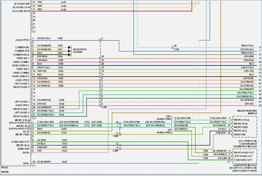
Understanding the Wiring Diagram Symbols
A wiring diagram uses symbols to represent the various components and connections in the circuit. Understanding these symbols is essential for interpreting the diagram correctly.
- Lines: Lines represent wires. Solid lines indicate a direct connection, while dashed lines may indicate a shielded wire or a ground connection. The thickness of the line doesn't necessarily represent wire gauge.
- Colors: Each wire is assigned a specific color code (e.g., Red, Black, Yellow, Green). The color code is often abbreviated (e.g., Red = RD, Black = BK). These color codes are critical for identifying the correct wires in the harness.
- Icons: Icons represent components such as the radio (often a rectangle with speaker symbols), speakers (a circle with a plus and minus sign), fuses (a zig-zag line within a rectangle), and grounds (a series of descending lines).
- Connector Symbols: Connectors are typically represented by rectangular or circular shapes with pins or terminals indicated.
- Splices: A splice is where multiple wires are joined together. It's usually indicated by a dot or a small circle where lines intersect.
The diagram will also include labels indicating the function of each wire (e.g., "12V Constant," "Left Front Speaker +"). Pay close attention to these labels to ensure you are connecting the wires correctly.
How the Radio Wiring Works
The radio wiring harness serves as the central nervous system for the audio system. Power is supplied through the 12V constant and ignition wires, allowing the radio to operate. The ground wire provides the necessary return path for the electrical current. When the radio is turned on, it processes audio signals and sends them to the speakers through the speaker wires. The antenna receives radio signals and transmits them to the radio for decoding. Illumination and dimmer wires control the radio's display lighting, and the remote turn-on wire activates external amplifiers.
Essentially, the harness provides all the necessary electrical connections for the radio to function properly.
Real-World Use: Basic Troubleshooting Tips
Here are a few common troubleshooting scenarios and how the wiring diagram can help:
- No Power to Radio: Use a multimeter to check for voltage on the 12V constant and ignition wires. If there's no voltage, check the corresponding fuses. The diagram will show you which fuse protects the radio circuit. Also, check the ground connection to ensure it's clean and secure.
- Speakers Not Working: Use a multimeter to check for continuity between the radio and the speakers. If there's no continuity, there may be a break in the wire or a faulty speaker. The diagram helps you identify the correct speaker wires and trace them from the radio to the speakers.
- Distorted Sound: Distorted sound can be caused by a faulty speaker or a problem with the wiring. Check the speaker wires for damage or corrosion. Try swapping the speaker wires to see if the problem moves to a different speaker.
- Radio Turns On But No Sound: Check the antenna connection. If the antenna is not properly connected, the radio may not be able to receive a signal. Also, check the amplifier turn-on wire if your vehicle has a factory amplifier.
Safety Considerations
Working with automotive electrical systems can be dangerous. Here are some important safety precautions:
- Disconnect the Battery: Always disconnect the negative terminal of the battery before working on the electrical system. This prevents accidental shorts and shocks. This is absolutely crucial.
- Use Proper Tools: Use insulated tools to avoid electrical shocks.
- Avoid Working in Wet Conditions: Water can conduct electricity, increasing the risk of shocks.
- Identify High-Current Circuits: Be aware of high-current circuits such as the power wires to the radio. Avoid shorting these circuits, as they can cause damage to the vehicle's electrical system or even start a fire.
- Double-Check Your Work: Before reconnecting the battery, double-check all your connections to ensure they are correct and secure.
Remember, if you are not comfortable working with automotive electrical systems, it's always best to consult a qualified professional.
We have the complete 2002 Dodge Ram 1500 Radio Wiring Harness Diagram available for download. This detailed schematic will provide all the necessary information to perform your audio upgrades or repairs with confidence. Be sure to use it in conjunction with the guidelines outlined in this article.