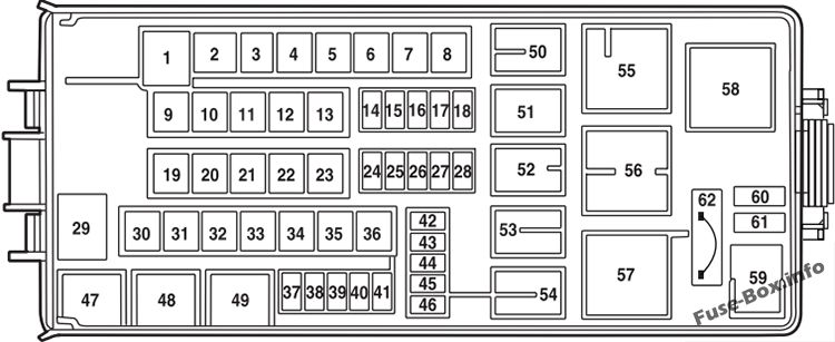
2002 Ford Explorer Fuse Box Diagram Under Hood
Understanding your 2002 Ford Explorer's under-hood fuse box is crucial for a variety of reasons, from basic troubleshooting to more complex modifications. This guide will provide a detailed breakdown of the fuse box diagram, empowering you to confidently diagnose and address electrical issues. We'll cover everything from the purpose of the diagram and its key components to interpreting the symbols and even some real-world troubleshooting tips. Consider this your in-depth manual for navigating the electrical heart of your Explorer.
Purpose of the Under-Hood Fuse Box Diagram
Why even bother with a fuse box diagram? The answer is simple: it's the key to understanding and managing your vehicle's electrical system. Here’s why it’s so important:
- Troubleshooting Electrical Problems: When a specific electrical component fails – a headlight, the windshield wipers, or even the radio – the fuse box is the first place you should look. The diagram pinpoints the fuse responsible for that circuit, allowing you to quickly identify a blown fuse.
- Performing Repairs: Knowing the function of each fuse and relay is invaluable when repairing or replacing electrical components. For example, if you're replacing a faulty fuel pump, the diagram tells you which fuse to check first.
- Making Modifications: If you're adding aftermarket accessories like amplifiers, lights, or a new alarm system, you need to tap into the vehicle's electrical system safely. The diagram helps you identify suitable circuits and avoid overloading existing ones.
- Preventative Maintenance: Periodically inspecting the fuses can catch potential problems before they escalate. A corroded or loose fuse could indicate a larger issue within that circuit.
- Educational Tool: Simply put, studying the diagram deepens your understanding of how your vehicle's electrical system is organized.
Key Specs and Main Parts
The under-hood fuse box in the 2002 Ford Explorer (and similar models from that era) is typically located on the driver's side of the engine compartment, near the battery. It's enclosed in a protective plastic housing with a latch or clips to secure the cover. Key components include:
- Fuses: These are the sacrificial elements designed to protect circuits from overcurrent. They contain a thin wire that melts and breaks the circuit if the current exceeds a safe level. Fuses are rated in amperes (amps), indicating the maximum current they can handle. Common amp ratings include 5A, 10A, 15A, 20A, 25A, and 30A.
- Relays: These are electromechanical switches that use a small current to control a larger current. They're often used to switch power to high-current devices like headlights, the fuel pump, and the starter motor. A relay consists of a coil, a set of contacts (normally open or normally closed), and a control circuit.
- Circuit Breakers: Unlike fuses, circuit breakers can be reset. They trip (open the circuit) when an overcurrent condition is detected and can be manually reset after the fault is cleared. While less common than fuses in the main fuse box, they might be present for certain high-demand circuits.
- Fuse Puller: This small plastic tool is used to safely remove fuses without damaging them or the fuse box terminals. It usually clips onto the fuse box cover.
- The Diagram Itself: Usually found on the inside of the fuse box cover, this diagram is your roadmap to the electrical system. It shows the location of each fuse and relay, along with its corresponding circuit and amperage rating.
Understanding Symbols and Markings
The fuse box diagram uses a system of symbols and markings to convey information. Here’s a breakdown of the common elements:
- Lines and Colors: The diagram primarily uses lines to represent electrical circuits. Color-coding, while not always present *on* the diagram itself (it’s usually black and white), is *within* the wiring harness of the vehicle. The diagram will *label* the specific color of the wire though, such as "LG/BK" for Light Green with a Black stripe. This helps trace wires throughout the vehicle.
- Fuse Symbols: Fuses are typically represented by a zigzag line or a rectangle with a squiggly line inside. Some diagrams may use a simpler rectangle. The amperage rating (e.g., 20A) is usually printed next to the symbol.
- Relay Symbols: Relays are often depicted as a square or rectangle containing a coil symbol (a looped wire) and switch contacts (a line with an arrow). The diagram will label the relay function (e.g., "Fuel Pump Relay").
- Component Icons: Many diagrams use icons to represent the components powered by each fuse. These can include symbols for headlights, windshield wipers, radios, and other accessories.
- Numerical and Alphanumeric Designations: Each fuse and relay is assigned a unique number or code (e.g., "Fuse 22" or "Relay R1"). This designation is used to identify the component in the diagram and on the fuse box itself.
How It Works: The Fuse Box in Action
The fuse box is the central distribution point for electrical power in your Explorer. Power flows from the battery to the fuse box, and then is distributed to various circuits throughout the vehicle. Each circuit is protected by a fuse or circuit breaker. If a short circuit or overload occurs in a particular circuit, the fuse blows, interrupting the flow of current and preventing damage to the wiring and components. Relays act as remote-controlled switches, allowing low-current circuits to control high-current devices.
Think of it like this: The fuse box is the electrical "firewall" of your car. When something goes wrong, the fuses are designed to sacrifice themselves to protect the rest of the system.
Real-World Use: Basic Troubleshooting Tips
Here’s how to use the fuse box diagram to troubleshoot common electrical problems:
- Identify the Problem: Determine which electrical component is not working.
- Consult the Diagram: Locate the fuse or relay associated with that component in the diagram.
- Inspect the Fuse: Use the fuse puller to remove the fuse. Hold it up to the light and check if the wire inside is broken. If it is, the fuse is blown.
- Test the Fuse (Optional): Use a multimeter to test the fuse for continuity. A good fuse will have continuity (a reading of 0 ohms), while a blown fuse will have no continuity (an open circuit).
- Replace the Fuse: If the fuse is blown, replace it with a new fuse of the same amperage rating. Never use a fuse with a higher amperage rating, as this could damage the wiring and components.
- Check the Circuit: If the new fuse blows immediately, there is a short circuit or overload in the circuit. This requires further investigation and may involve checking the wiring, connectors, and the component itself.
- Relay Testing: Relays are more difficult to test, but you can often swap a suspected bad relay with a known good relay (of the same type) to see if the problem is resolved. You can also use a multimeter to test the relay's coil and contacts.
Safety Precautions
Working with automotive electrical systems can be dangerous if proper precautions are not taken. Keep these points in mind:
- Disconnect the Battery: Before working on the fuse box, always disconnect the negative terminal of the battery. This will prevent accidental short circuits and electrical shocks.
- Work in a Well-Lit Area: Ensure you have adequate lighting to see the fuse box and the diagram clearly.
- Use the Right Tools: Always use a fuse puller to remove fuses. Never use pliers or screwdrivers, as these can damage the fuse box terminals.
- Replace Fuses with the Correct Amperage: Using a fuse with a higher amperage rating can overload the circuit and cause a fire.
- Avoid Working on the Fuel Pump Circuit Without Depressurizing: The fuel pump circuit carries a significant amount of power and fuel vapor can be present. Always depressurize the fuel system before working on this circuit to prevent a fire hazard. This is extremely important.
- Be Careful Around Airbag Circuits: Airbag circuits are highly sensitive. Consult a professional if you suspect a problem with the airbag system. Improper handling can cause the airbags to deploy unexpectedly, resulting in serious injury.
Working on your 2002 Ford Explorer's electrical system can be a rewarding experience, but it's important to approach it with caution and a thorough understanding of the system. This guide provides a solid foundation for understanding the under-hood fuse box diagram and tackling basic electrical repairs. Remember, if you're unsure about any aspect of the electrical system, it's always best to consult a qualified mechanic. A shorted system can cause significant damage and can be potentially life-threatening. Proceed with care.
To further assist you, we have the 2002 Ford Explorer Under Hood Fuse Box Diagram file available for download. This file provides a detailed visual representation of the fuse box layout, making it easier to identify and locate the specific fuses and relays you need.