2002 Ford Explorer Sport Trac Fuse Diagram
The 2002 Ford Explorer Sport Trac, a unique blend of SUV and pickup truck, boasts a complex electrical system. Understanding its fuse layout is crucial for anyone tackling electrical repairs, modifications, or even routine maintenance. This article provides a detailed breakdown of the 2002 Ford Explorer Sport Trac fuse diagram, explaining its purpose, key components, symbols, and practical applications.
Why a Fuse Diagram Matters
A fuse diagram is essentially a roadmap of your vehicle's electrical protection system. Fuses are sacrificial components designed to protect sensitive circuits from overcurrent conditions. When a circuit draws excessive amperage (current), the fuse's internal element melts, breaking the circuit and preventing damage to more expensive components like wiring harnesses, control modules, and electronic devices. Knowing the location and function of each fuse is vital for:
- Troubleshooting electrical problems: Identifying a blown fuse associated with a malfunctioning component is the first step in diagnosing many electrical issues.
- Performing repairs: Replacing a blown fuse is often the simplest fix, saving time and money compared to taking the vehicle to a mechanic.
- Adding aftermarket accessories: Properly tapping into the electrical system for accessories like auxiliary lights or sound systems requires identifying appropriate fuse locations.
- Understanding your vehicle's electrical system: Studying the fuse diagram provides valuable insight into the layout and functionality of the electrical system.
Key Specs and Main Parts of the Fuse System
The 2002 Ford Explorer Sport Trac has two main fuse locations:
- The Interior Fuse Panel: Located under the dashboard, typically on the driver's side. This panel houses fuses protecting interior circuits like lights, radio, power windows, and door locks.
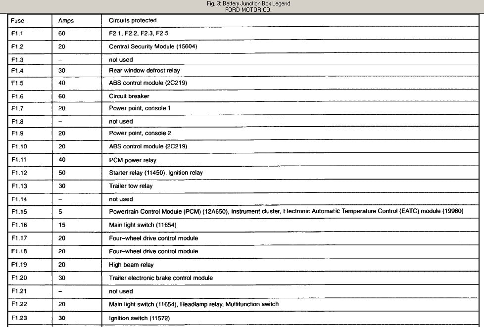
- The Power Distribution Box (PDB): Found in the engine compartment, usually near the battery. The PDB contains fuses and relays for high-current circuits such as the starter motor, alternator, fuel pump, and anti-lock braking system (ABS).
Key Specifications:
- Voltage: The entire electrical system is designed to operate at 12 Volts DC (Direct Current).
- Fuse Ratings: Fuses are rated in Amperes (Amps), indicating the maximum current they can handle before blowing. Common ratings include 5A, 7.5A, 10A, 15A, 20A, 25A, 30A, and 40A. Always replace a blown fuse with one of the same amperage rating.
- Fuse Types: Primarily blade-type fuses, also known as spade fuses, are used. These are color-coded according to their amperage rating.
Understanding Fuse Diagram Symbols and Conventions
Fuse diagrams use a standardized set of symbols and conventions to represent different components and connections. Understanding these symbols is key to interpreting the diagram accurately.
- Lines: Lines represent wires or electrical conductors. Thicker lines may indicate higher current capacity.
- Boxes: Boxes generally represent components like fuses, relays, or control modules.
- Circles: Circles can represent various components, depending on the context, such as sensors or lights.
- Relays: Relays are electromechanical switches used to control high-current circuits with a low-current signal. They are typically represented by a square with a coil symbol inside.
- Ground Symbols: Ground symbols indicate a connection to the vehicle's chassis, providing a return path for the electrical current.
- Color Coding: While the diagram itself might not be in color, the actual fuses are color-coded to denote their amperage rating. Use a fuse puller tool to extract the fuse and check its color before replacing it.
How the Fuse System Works
The electrical system operates on the principle of a closed circuit. Power flows from the battery, through the wiring, to the load (e.g., a light bulb or motor), and back to the battery through the ground. Each circuit is protected by a fuse. If there's a short circuit (an unintended path of low resistance to ground) or excessive current draw, the fuse element heats up rapidly and melts, interrupting the flow of electricity. This prevents damage to the wiring and components in that circuit. The Ohm's Law principle (Voltage = Current x Resistance) is central to how a fuse works. A lower resistance (short circuit) or higher voltage can lead to increased current, exceeding the fuse's rated amperage and causing it to blow.
Relays are used when a high-current circuit needs to be controlled by a low-current signal. For example, the headlight switch in the cabin may only control a small current, which is used to activate a relay in the engine compartment. This relay then switches on the high-current circuit that powers the headlights.
Real-World Use: Basic Troubleshooting Tips
Here's a basic troubleshooting procedure for electrical problems:
- Identify the Symptom: Determine which electrical component is not working.
- Consult the Fuse Diagram: Locate the fuse associated with that component in the interior fuse panel or the power distribution box diagram.
- Inspect the Fuse: Visually inspect the fuse. A blown fuse will typically have a broken filament inside. You can also use a multimeter to test for continuity across the fuse. A working fuse will show continuity (a reading of 0 ohms or a beep on the continuity setting).
- Replace the Fuse: Replace the blown fuse with a new fuse of the exact same amperage rating. Never use a fuse with a higher rating.
- Test the Circuit: After replacing the fuse, test the component to see if it now works.
- If the Fuse Blows Again: If the new fuse blows immediately or shortly after replacement, there is likely a short circuit or an overload condition in the circuit. Further diagnosis is required to locate and repair the fault. This might involve checking wiring for damage, inspecting components for shorts, or testing the amperage draw of the circuit.
Important Note: If a fuse repeatedly blows, it's a sign of a more serious problem. Do not simply keep replacing fuses. This could lead to overheating and potentially a fire.
Safety Precautions
Working on electrical systems involves some inherent risks. Take the following precautions:
- Disconnect the Battery: Before working on any electrical components, disconnect the negative (-) battery cable to prevent accidental short circuits.
- Use Insulated Tools: Use tools with insulated handles to reduce the risk of electric shock.
- Work in a Well-Lit Area: Ensure adequate lighting to clearly see what you are doing.
- Avoid Working in Wet Conditions: Water can conduct electricity, increasing the risk of shock.
- Be Careful Around High-Current Components: Components like the starter motor and alternator carry high currents and can generate significant heat. Avoid touching them immediately after the engine has been running.
- Airbags: Be extremely careful around airbags. Disconnecting the battery alone may not fully disable the airbag system. Consult a repair manual for proper airbag deactivation procedures.
Specifically, components associated with the engine starting system, like the starter solenoid and starter motor itself, carry very high amperage. Exercise extreme caution when working near these components, and ensure the battery is disconnected to prevent accidental engagement.
Understanding and using the 2002 Ford Explorer Sport Trac fuse diagram empowers you to diagnose and fix common electrical issues effectively. Remember to prioritize safety and consult a qualified mechanic for complex problems beyond your skill level. We have a downloadable copy of the 2002 Ford Explorer Sport Trac fuse diagram file available. This diagram will provide you with specific fuse locations and functions tailored to your vehicle's configuration.