
2002 Ford F150 Exhaust System Diagram
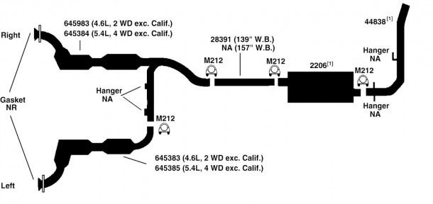
The exhaust system of your 2002 Ford F150 is a critical component responsible for channeling harmful combustion gases away from the engine, reducing emissions, and minimizing noise. Understanding its layout and individual components is invaluable for maintenance, troubleshooting, and even performance upgrades. This article provides a detailed breakdown of a typical 2002 Ford F150 exhaust system diagram, offering insights for experienced DIYers and modders.
Purpose of Understanding the Exhaust System Diagram
Why bother diving into the intricacies of an exhaust system diagram? Several reasons make it a worthwhile endeavor:
- Diagnostics and Repair: Identifying faulty components becomes significantly easier. A diagram pinpoints the location of oxygen sensors, catalytic converters, mufflers, and exhaust pipes, allowing you to trace leaks, inspect for damage, and replace worn-out parts accurately.
- Performance Upgrades: Planning exhaust modifications, such as installing a cat-back system or headers, requires a solid understanding of the existing system. A diagram reveals pipe diameters, connection points, and potential clearance issues.
- Emission Compliance: Knowing the components responsible for emissions control, like the catalytic converter and oxygen sensors, helps ensure your vehicle meets legal requirements and avoids failing emissions tests.
- General Knowledge: Enhancing your understanding of your vehicle's inner workings empowers you to make informed decisions about maintenance and repairs.
Key Specs and Main Parts of the 2002 Ford F150 Exhaust System
The 2002 Ford F150 came with various engine options, primarily the 4.2L V6, 4.6L V8, and 5.4L V8. Exhaust system configurations varied slightly depending on the engine and drivetrain (2WD or 4WD). However, the core components and their functions remain consistent:
- Exhaust Manifolds (or Headers): These bolt directly to the engine cylinder heads and collect exhaust gases from each cylinder. They are typically made of cast iron. Aftermarket headers offer improved flow and performance but may require modifications.
- Y-Pipe (or H-Pipe): On V-engines, the exhaust manifolds typically connect to a Y-pipe (if the vehicle has a single exhaust system) or an H-pipe (if it has a dual exhaust system). These pipes merge the exhaust flow from both banks of the engine.
- Catalytic Converter(s): This is a crucial component for reducing harmful emissions. It uses catalysts to convert pollutants like hydrocarbons (HC), carbon monoxide (CO), and nitrogen oxides (NOx) into less harmful substances. The 2002 F150 can have one or two catalytic converters, depending on the engine and configuration.
- Oxygen Sensors (O2 Sensors): These sensors monitor the oxygen content in the exhaust gas and provide feedback to the engine control unit (ECU). There are typically two sets of O2 sensors: upstream sensors (before the catalytic converter) and downstream sensors (after the catalytic converter). Upstream sensors are crucial for fuel management, while downstream sensors monitor the efficiency of the catalytic converter.
- Muffler: The muffler reduces exhaust noise. It uses internal baffles and resonators to dampen sound waves. Many aftermarket mufflers offer different sound characteristics.
- Tailpipe: This is the final section of the exhaust system, which directs the exhaust gases away from the vehicle.
- Exhaust Pipes: These are the connecting pipes that link all the other components together.
- Hangers and Mounts: Rubber hangers and metal mounts support the exhaust system and isolate it from the vehicle's chassis to prevent vibrations and noise.
- Flanges and Gaskets: These components create sealed connections between the various exhaust system parts. Exhaust leaks can occur if flanges are corroded or gaskets are damaged.
Understanding Symbols in an Exhaust System Diagram
Exhaust system diagrams typically use standardized symbols and conventions:
- Lines: Solid lines usually represent exhaust pipes. Thicker lines might indicate larger diameter pipes. Dotted lines might indicate heat shields or mounting points.
- Boxes/Rectangles: These typically represent components like catalytic converters, mufflers, or resonators. The diagram might include labels or abbreviations inside the box to identify the component.
- Circles: Circles often represent sensors, such as oxygen sensors. The type of sensor is usually indicated by a label next to the circle (e.g., "O2S11" for Oxygen Sensor Bank 1, Sensor 1).
- Arrows: Arrows indicate the direction of exhaust gas flow.
- Color Coding: While not always present, some diagrams use color coding to differentiate between different types of pipes or components. For example, a specific color might represent stainless steel piping versus aluminized steel piping.
- Abbreviations: Common abbreviations include: CAT (Catalytic Converter), MUFF (Muffler), O2S (Oxygen Sensor), EGR (Exhaust Gas Recirculation), MAN (Manifold).
Pay close attention to the legend or key provided with the diagram, as it will explain the specific symbols and conventions used in that particular diagram.
How the Exhaust System Works
The exhaust system's primary function is to safely and efficiently remove combustion byproducts from the engine. Here's a simplified explanation of how it works:
- Combustion Gases Exit the Engine: Hot exhaust gases are expelled from the engine cylinders and enter the exhaust manifolds (or headers).
- Gases Merge (V-engines): On V-engines, the exhaust gases from both cylinder banks merge into a single pipe (Y-pipe) or two pipes (H-pipe).
- Emissions Reduction: The exhaust gases pass through the catalytic converter(s), where harmful pollutants are converted into less harmful substances.
- Oxygen Monitoring: Oxygen sensors monitor the oxygen content of the exhaust gases before and after the catalytic converter(s). This information is used by the ECU to optimize fuel mixture and monitor the efficiency of the catalytic converter.
- Noise Reduction: The exhaust gases then flow through the muffler, which reduces noise levels.
- Exhaust Gases Exit: Finally, the exhaust gases are expelled from the vehicle through the tailpipe.
Real-World Use: Basic Troubleshooting Tips
Understanding your exhaust system diagram can greatly assist in troubleshooting common problems:
- Exhaust Leaks: Listen for hissing or ticking noises coming from the exhaust system, especially near joints, flanges, or the manifold. Use the diagram to pinpoint potential leak locations. Visual inspection for soot buildup can also help identify leaks.
- Catalytic Converter Failure: Symptoms include reduced engine performance, poor fuel economy, and a rotten egg smell. Use the diagram to locate the catalytic converter and visually inspect it for damage. A diagnostic scan tool can also help identify catalytic converter efficiency issues.
- Oxygen Sensor Problems: Faulty oxygen sensors can trigger the "Check Engine" light. Use the diagram to identify the location of the affected sensor and replace it. Remember to use the correct type of oxygen sensor for your vehicle.
- Excessive Noise: A rattling or booming noise from the exhaust system could indicate a damaged muffler, resonator, or exhaust pipe. Use the diagram to visually inspect these components for damage.
Safety Precautions
Working on an exhaust system can be dangerous due to the extreme temperatures involved and the potential for exposure to harmful gases. Always follow these safety precautions:
- Allow the Exhaust System to Cool: Never work on an exhaust system while it is hot. Allow sufficient time for it to cool completely to prevent burns.
- Wear Safety Glasses: Protect your eyes from debris and metal shards.
- Wear Gloves: Protect your hands from cuts and burns.
- Work in a Well-Ventilated Area: Exhaust fumes contain carbon monoxide, which is a deadly gas. Ensure adequate ventilation to prevent carbon monoxide poisoning.
- Use Jack Stands: If you need to raise the vehicle, use jack stands to support it securely. Never rely solely on a jack.
- Be Careful with Torches: If you need to use a torch to cut or weld exhaust pipes, take extreme care to avoid starting a fire. Have a fire extinguisher readily available.
The catalytic converter gets extremely hot during operation and can cause severe burns. Be extremely careful when working near it, even after the engine has been off for a while. Never touch the catalytic converter immediately after driving.
Disclaimer: This article provides general information about the 2002 Ford F150 exhaust system. Specific configurations and components may vary depending on the engine, drivetrain, and trim level. Always consult your vehicle's repair manual or a qualified mechanic for accurate information and repair procedures.
We have a downloadable exhaust system diagram file for the 2002 Ford F150. It's a valuable resource for anyone looking to understand, maintain, or modify their vehicle's exhaust system. This detailed diagram provides a visual representation of the exhaust system's components, their locations, and connections. With this diagram, you'll be better equipped to diagnose issues, plan upgrades, and ensure your exhaust system is functioning optimally. Contact us to obtain the file.