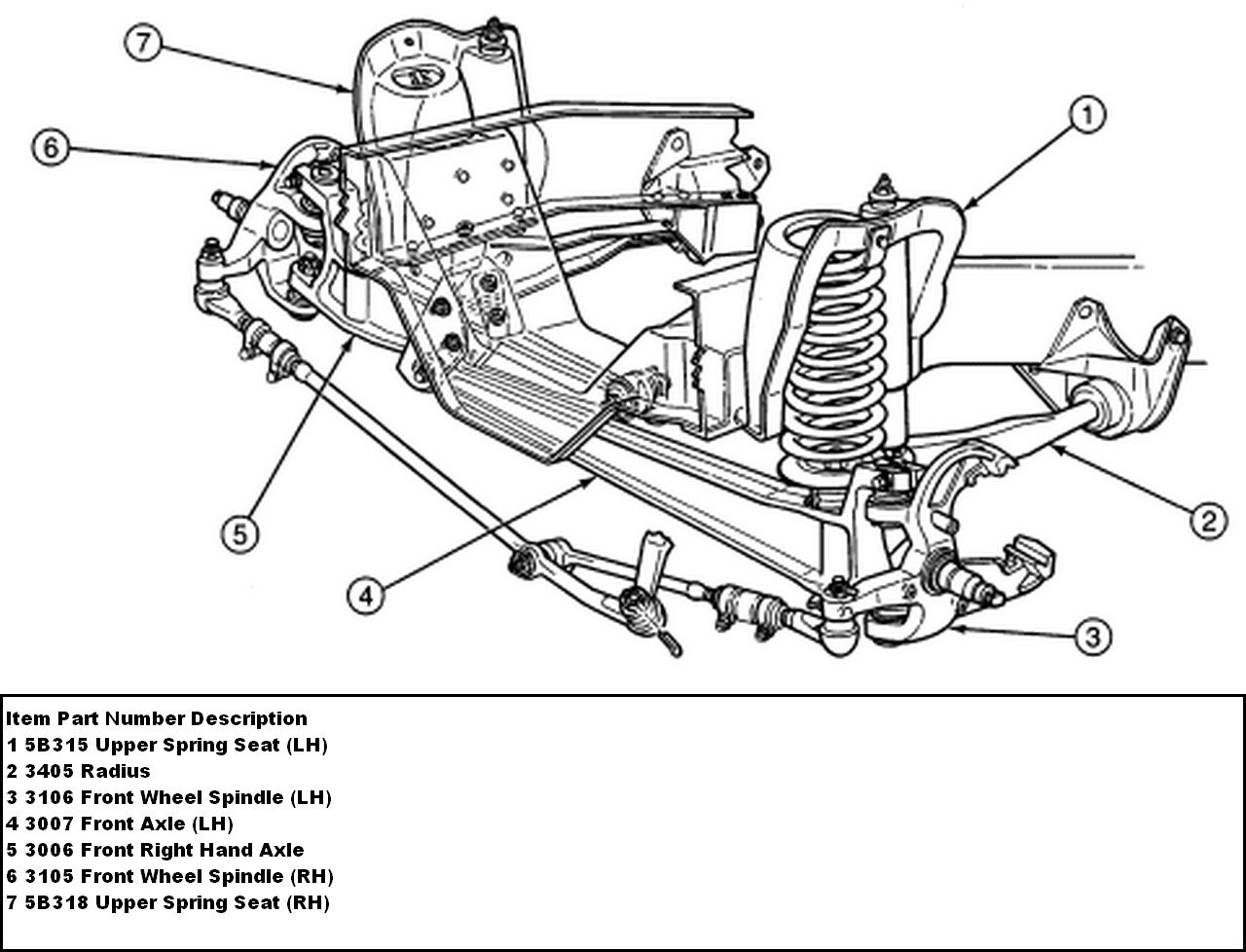
2002 Ford F150 Front Suspension Diagram
The 2002 Ford F-150 is a beloved truck known for its reliability and ruggedness. A critical component of its handling and ride quality is its front suspension system. Understanding the front suspension is essential for anyone looking to perform maintenance, diagnose issues, or even consider modifications. This article will delve into a detailed breakdown of the 2002 Ford F-150 front suspension diagram, providing you with the knowledge to confidently tackle related projects.
Purpose of Understanding the Diagram
Why is a front suspension diagram important? Simply put, it's your roadmap for navigating the complex world of your truck's front end. It serves several crucial purposes:
- Repair and Maintenance: The diagram allows you to visually identify parts, understand their relationship to each other, and pinpoint potential problem areas. Whether you're replacing worn ball joints, shocks, or control arms, the diagram ensures you're working on the correct component.
- Diagnosis: When diagnosing suspension issues like clunking noises, uneven tire wear, or poor handling, the diagram helps you systematically analyze the system to identify the root cause. It allows you to trace the flow of forces and understand how different components contribute to the overall performance.
- Modification and Upgrades: If you're considering lifting your truck, upgrading shocks, or installing aftermarket control arms, the diagram provides a vital reference for understanding the impact of these changes on the entire suspension system. It helps you plan your modifications safely and effectively.
- Learning and Understanding: Even if you don't plan on wrenching on your truck yourself, understanding the diagram enhances your overall knowledge of automotive mechanics and allows you to communicate more effectively with your mechanic.
Key Specs and Main Parts
The 2002 Ford F-150 typically utilizes a Double Wishbone or Independent Front Suspension (IFS) system. While variations might exist based on 2WD or 4WD models, the fundamental principles remain the same. Here are the key components:
- Upper Control Arm (A-Arm): This arm connects the upper portion of the steering knuckle to the vehicle's frame. It allows for vertical movement while maintaining wheel alignment.
- Lower Control Arm (A-Arm): Similar to the upper control arm, but positioned lower. It bears a significant portion of the vehicle's weight and provides a stable platform for the suspension.
- Steering Knuckle: This component houses the wheel hub, bearings, and brake assembly. It connects to the control arms via ball joints and pivots to allow for steering.
- Ball Joints: These spherical bearings connect the control arms to the steering knuckle, allowing for articulation and movement in multiple directions. They are critical for steering and suspension function.
- Shock Absorber (Damper): Controls the oscillations of the suspension spring, preventing excessive bouncing and improving ride comfort and handling.
- Coil Spring (or Torsion Bar in some 4WD models): Provides the primary suspension support, absorbing bumps and maintaining vehicle ride height.
- Sway Bar (Stabilizer Bar): Connects the left and right sides of the suspension, reducing body roll during cornering.
- Wheel Hub and Bearings: The hub is the central part of the wheel assembly, and the bearings allow the wheel to rotate smoothly.
- Tie Rod Ends (Inner and Outer): These connect the steering rack to the steering knuckle, transmitting steering input to the wheels.
Understanding Symbols in the Diagram
A suspension diagram isn't just a picture; it's a technical drawing with specific symbols and conventions. While the exact appearance can vary slightly depending on the source, here are some common interpretations:
- Solid Lines: Typically represent solid mechanical connections between components, such as bolts, welds, or direct contact.
- Dashed Lines: Might indicate hidden lines (parts obscured by others in the view) or represent fluid lines (brake lines, etc.).
- Different Colors: Some diagrams use colors to differentiate components or indicate materials (e.g., blue for steel, green for rubber). Always refer to the diagram's legend.
- Arrows: Show direction of movement, force, or fluid flow.
- Abbreviations: Common abbreviations include UCA (Upper Control Arm), LCA (Lower Control Arm), and SB (Sway Bar).
- Torque Specifications: Often included near bolt locations, indicating the recommended torque value for tightening.
Always use a torque wrench to ensure proper tightening and avoid damage.
How It Works
The 2002 F-150's front suspension is designed to provide a comfortable ride while maintaining stable handling. Here's a simplified explanation of how it works:
- Bump Encounter: When a wheel encounters a bump, it moves upwards.
- Spring Compression: This upward movement compresses the coil spring (or twists the torsion bar), absorbing the impact energy.
- Damping Action: The shock absorber restricts the speed of the spring's compression and rebound, preventing excessive bouncing.
- Control Arm Movement: The upper and lower control arms pivot, allowing the wheel to move vertically while maintaining its alignment.
- Sway Bar Resistance: During cornering, the sway bar resists body roll by transferring force from one side of the suspension to the other.
- Steering Input: When you turn the steering wheel, the steering rack moves the tie rod ends, which in turn pivot the steering knuckles, causing the wheels to turn.
The interplay of these components allows the suspension to absorb shocks, maintain tire contact with the road, and provide a controlled and comfortable driving experience.
Real-World Use: Basic Troubleshooting Tips
The front suspension is subject to wear and tear. Here are some common issues and how the diagram can help you troubleshoot:
- Clunking Noise: Often caused by worn ball joints, tie rod ends, or sway bar bushings. Use the diagram to locate these components and visually inspect them for play or damage.
- Uneven Tire Wear: Can indicate alignment issues caused by worn ball joints, tie rod ends, or bent control arms. The diagram will help you identify these components for inspection.
- Poor Handling: May be due to worn shocks, broken springs, or loose suspension components. The diagram will guide you in checking the condition of these parts.
- Squeaking Noise: Often caused by dry or worn ball joints or bushings. The diagram allows you to pinpoint these areas and apply lubricant or replace the worn parts.
Example: You hear a clunking noise when going over bumps. Using the diagram, you locate the ball joints on the lower control arm. You visually inspect them and notice excessive play. This confirms that the ball joints are likely the cause of the noise and need to be replaced.
Safety Considerations
Working on the front suspension can be dangerous due to the potential energy stored in the springs and the presence of heavy components. Always prioritize safety:
- Spring Compression: Coil springs store a tremendous amount of energy. Never attempt to disassemble a suspension without using a proper spring compressor. Improper use can result in serious injury or death.
- Vehicle Support: Always use jack stands to support the vehicle before working underneath it. Never rely solely on a jack.
- Brake Lines: Be careful not to damage brake lines when working on the suspension. Damage to brake lines can result in brake failure.
- Torque Specifications: Always use a torque wrench to tighten bolts to the specified torque values. Overtightening or undertightening can lead to component failure.
- Wheel Alignment: After replacing any suspension components that affect alignment (ball joints, tie rod ends, control arms), it's essential to have the vehicle professionally aligned.
Before starting any suspension work, consult the vehicle's service manual for specific instructions and safety precautions. If you are not comfortable performing the work yourself, it's best to consult a qualified mechanic.
With a clear understanding of the 2002 Ford F-150 front suspension diagram and the safety considerations involved, you'll be well-equipped to tackle basic maintenance, diagnose issues, and even consider modifications to your truck's front suspension system. Remember to always prioritize safety and consult the vehicle's service manual for specific instructions.
We have a downloadable version of the 2002 Ford F-150 Front Suspension Diagram available for your convenience. This visual aid can be invaluable when performing repairs, troubleshooting, or simply gaining a better understanding of your truck's mechanics. Contact us for access to the file.