2002 Ford F150 Stereo Wiring Diagram
Let's dive into the intricacies of the 2002 Ford F150 stereo wiring diagram. Whether you're battling a finicky factory head unit, upgrading your sound system with aftermarket components, or simply trying to understand how your audio system is wired, this diagram is your roadmap. We’ve got the full diagram available for download, which we'll mention again later. But first, let's break down what you need to know.
Purpose of the Wiring Diagram
A stereo wiring diagram isn't just a piece of paper; it's a critical tool for several reasons:
- Troubleshooting: When your radio suddenly cuts out, or a speaker stops working, the diagram helps you trace the signal path and identify the faulty component.
- Aftermarket Installation: Installing a new head unit, amplifier, or speakers requires understanding the existing wiring to avoid shorts, blown fuses, or damage to your vehicle's electrical system.
- Component Identification: The diagram labels each wire and its function, allowing you to confidently connect new devices without guesswork.
- Learning: Even if you're not actively working on your stereo, studying the diagram provides valuable insight into automotive electrical systems.
Key Specs and Main Parts of the 2002 Ford F150 Stereo System
The 2002 Ford F150's factory stereo system is relatively straightforward. Understanding its core components is crucial before interpreting the wiring diagram. The main parts consist of:
- Head Unit (Radio): This is the central control unit, providing the user interface (buttons, display), tuner for radio frequencies (AM/FM), and pre-amplification of the audio signal. The factory unit typically has outputs for four speakers (front left, front right, rear left, rear right).
- Speakers: Usually, the F150 had speakers in the front doors and rear of the cab (either in the rear doors on SuperCab models or behind the seats on regular cab models). The speaker impedance (typically 4 ohms) is essential for amplifier matching.
- Wiring Harness: This is the collection of wires connecting the head unit to the speakers, power source, ground, and other accessories (e.g., antenna). The wiring harness plugs into the back of the head unit.
- Antenna: The antenna receives radio signals and sends them to the head unit.
- Amplifier (Optional): Some higher-end F150 models came with a factory amplifier to boost the audio signal. If your truck has one, it will typically be located under one of the seats or behind the dashboard.
Key Specs:
- Voltage: The system operates on 12V DC (Direct Current).
- Speaker Impedance: Typically 4 Ohms (check your specific speakers).
- Wire Gauge: Wire gauges vary, with power wires often being thicker (lower gauge number) than speaker wires.
Decoding the Symbols on the Wiring Diagram
Understanding the symbols on the wiring diagram is key to deciphering its information. Here's a breakdown of common symbols:
- Solid Lines: Represent wires. The thickness of the line may indicate the wire gauge.
- Dotted Lines: Usually represent shielding or ground connections.
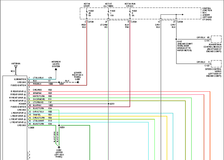
- Color Codes: Each wire is identified by a color code (e.g., Red, Black, White/Green). These codes are crucial for matching wires during installation or repair. The diagram will usually provide a key to the color codes, such as "RD = Red, BK = Black, WH/GR = White with Green Stripe."
- Ground Symbol: A triangle pointing downwards or a series of lines decreasing in size, indicating a connection to the vehicle's chassis ground.
- Connector Symbols: Squares or circles with numbers inside, representing connectors that join different sections of the wiring harness. These numbers are important for locating specific connectors within the vehicle.
- Component Symbols: Rectangles representing components like the head unit, speakers, and amplifier. These components are labeled with their function (e.g., "Radio," "Left Front Speaker").
- Fuse Symbol: A wavy line inside a rectangle, indicating a fuse. The diagram will usually specify the fuse amperage rating.
How the Stereo System Works
The basic operation of the stereo system follows this sequence:
- Power Supply: The head unit receives power from the vehicle's battery through the ignition switch and a fuse. This provides power for the unit to operate.
- Signal Source: The head unit receives audio signals from various sources, such as the radio tuner (AM/FM), a CD player (if equipped), or auxiliary input.
- Signal Processing: The head unit processes the audio signal, allowing you to adjust the volume, tone (bass, treble), and balance (left/right, front/rear).
- Amplification: The head unit pre-amplifies the audio signal to a low-level output. If an external amplifier is present, the signal is sent to the amplifier for further amplification.
- Speaker Output: The amplified audio signal is sent to the speakers through the wiring harness.
- Sound Production: The speakers convert the electrical signal into sound waves.
The wiring diagram illustrates these steps, showing how each component is connected and how the signal flows through the system. Understanding the signal flow helps you pinpoint the source of audio problems. For example, if the radio works but the CD player doesn't, you know to focus your attention on the CD player input and its associated wiring.
Real-World Use: Basic Troubleshooting Tips
Here are some practical troubleshooting tips using the wiring diagram:
- No Power to the Radio: Check the fuse first! Use the diagram to locate the correct fuse in the fuse box. If the fuse is blown, replace it with one of the same amperage rating. If it blows again immediately, there's likely a short circuit in the wiring. Use the wiring diagram to trace the power wire from the fuse to the head unit, looking for damaged insulation or loose connections.
- One Speaker Not Working: Use a multimeter to check the speaker wiring for continuity (a complete circuit). Disconnect the speaker and measure the resistance across its terminals. A reading of around 4 ohms (or whatever the speaker's impedance is) indicates a good speaker. If there's no continuity or a very high resistance, the speaker is likely bad. Also check the wiring between the head unit and the speaker, looking for breaks or loose connections.
- Distorted Sound: Distorted sound can be caused by a blown speaker, a damaged amplifier, or a wiring problem. Check the speaker wiring for shorts to ground. Also, inspect the amplifier (if equipped) for signs of damage.
- Intermittent Problems: Intermittent problems are often caused by loose connections or corroded terminals. Carefully inspect all connectors and terminals in the wiring harness, cleaning them with electrical contact cleaner if necessary.
Safety Precautions
Working with automotive electrical systems can be dangerous. Take these precautions:
- Disconnect the Battery: Always disconnect the negative (-) battery terminal before working on any electrical components. This prevents accidental shorts and potential damage to your vehicle's electrical system.
- Use Proper Tools: Use insulated tools to avoid electrical shocks. A multimeter is essential for testing circuits and identifying problems.
- Avoid Water: Never work on electrical components in wet conditions.
- Be Careful with Airbags: The F150's airbag system is sensitive to electrical interference. Avoid tampering with any wiring near the airbag module without proper training.
- Fuses: Never replace a fuse with one of a higher amperage rating. This can overload the circuit and cause a fire.
The wiring diagram shows the location of the radio's power source, which is a hot circuit even with the ignition off, which is why disconnecting the battery is very important. The airbag system also has high energy storage components, so avoid direct contact with those related wires.
Conclusion
The 2002 Ford F150 stereo wiring diagram is an invaluable resource for anyone working on their truck's audio system. By understanding the symbols, components, and signal flow, you can confidently troubleshoot problems, install aftermarket equipment, and enhance your listening experience. Always prioritize safety and take your time to avoid costly mistakes.
And as promised, you can download the full 2002 Ford F150 Stereo Wiring Diagram file here. Good luck with your project!