2002 Ford F250 Super Duty Fuse Panel Diagram
Alright, let's dive into the fuse panel diagram for your 2002 Ford F250 Super Duty. Whether you're tackling electrical gremlins, planning an aftermarket modification, or just want a deeper understanding of your truck's inner workings, understanding this diagram is absolutely crucial. Think of it as the Rosetta Stone for your F250's electrical system.
Purpose: Unlocking Your F250's Electrical Secrets
Why bother with a fuse panel diagram? Simple: it’s essential for:
- Troubleshooting Electrical Problems: A blown fuse is often the first sign of an issue. The diagram tells you exactly which circuit that fuse protects, narrowing down your search area.
- Planning Aftermarket Installations: Adding accessories like lights, winches, or upgraded stereos requires tapping into the existing electrical system. Knowing which fuses control what allows you to do so safely and effectively, choosing appropriate circuits and avoiding overloading.
- Preventing Further Damage: Replacing a blown fuse with the wrong amperage can lead to more serious problems, including short circuits, melted wiring, and even fires. The diagram ensures you're using the correct replacement fuse.
- General Understanding: Simply understanding how your truck's electrical system is laid out gives you a better grasp of how all its components interact.
Key Specs and Main Parts of the Fuse Panel
The 2002 Ford F250 Super Duty typically has two main fuse panel locations:
- Interior Fuse Panel: Located under the dashboard, usually on the driver's side, near the kick panel. This panel primarily handles interior circuits like lights, the radio, power windows, and the instrument cluster.
- Under-Hood Fuse/Relay Box: Situated in the engine compartment, often near the battery. This houses fuses and relays for high-current systems like the starter motor, fuel pump, headlights, and various engine management components.
Each fuse panel houses:
- Fuses: These are sacrificial components designed to protect circuits from overcurrent. They contain a thin metal strip that melts and breaks the circuit when the current exceeds a specific rating. Common fuse types include blade fuses (ATO, ATC, Mini) and cartridge fuses.
- Relays: Electromagnetic switches that allow a low-current circuit to control a high-current circuit. They're essential for systems like headlights, starters, and fuel pumps, where the switch on the dashboard can't handle the full current draw.
- Circuit Breakers: Similar to fuses, but they can be reset after tripping. They're less common in these panels but may be used for certain high-demand circuits.
- Fuse Puller: A small plastic tool for safely removing fuses without damaging them or the surrounding components.
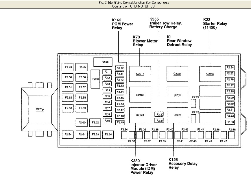
The diagram itself is a critical component. It typically shows a top-down view of the fuse panel, with each fuse and relay clearly labeled with its amperage rating and the circuit it protects. Look for labels like "Radio," "Headlights," "Fuel Pump," "PCM," etc.
Decoding the Symbols: Your Electrical Language Guide
Fuse panel diagrams use a variety of symbols to convey information efficiently. Here's a breakdown of common elements:
- Lines: Solid lines represent wires, while dashed lines may indicate shielded wires or connections to ground. The thickness of the line doesn't typically represent wire gauge on these diagrams.
- Colors: Wire colors are often indicated next to the lines or on a separate key. Common colors include red (power), black (ground), yellow, blue, green, and white. Knowing the wire color helps you trace the circuit through the vehicle.
- Fuse Symbols: Typically represented by a rectangle with a wavy line inside, or a simplified representation of the fuse itself. The amperage rating (e.g., "15A," "20A") is usually printed nearby.
- Relay Symbols: A square or rectangle with internal symbols representing the coil and contacts of the relay. The diagram may indicate the relay's function (e.g., "Fuel Pump Relay," "Headlight Relay").
- Component Symbols: Simplified representations of the components being powered (e.g., a light bulb for headlights, a speaker for the radio).
- Ground Symbols: Represented by a series of downward-pointing lines, indicating a connection to the vehicle's chassis (ground).
Understanding these symbols allows you to "read" the diagram and trace the flow of electricity through the circuit.
How It Works: From Battery to Component
The electrical system starts at the battery. From there, power is distributed through the vehicle's wiring harness. Before reaching individual components, the electricity passes through the fuse panel. Here's how it works:
- Power Source: The battery provides the initial voltage (12V in most automotive systems).
- Fuse Protection: The fuse acts as a weak link in the circuit. If the current exceeds the fuse's rating, the fuse blows, breaking the circuit and preventing damage to other components.
- Component Activation: Once the fuse is intact, electricity flows to the intended component (e.g., a headlight bulb).
- Ground Return: After powering the component, the electricity returns to the battery through the vehicle's chassis (ground). This completes the circuit.
Relays play a crucial role in many circuits. A low-current signal from a switch activates the relay's coil, which then closes the contacts, allowing a high-current circuit to power a component like the starter motor.
Real-World Use: Basic Troubleshooting Tips
Here are a few practical troubleshooting scenarios where the fuse panel diagram comes in handy:
- Headlights Not Working: Check the fuse labeled "Headlights" (or "HL"). If it's blown, replace it with the same amperage rating. If it blows again immediately, there's likely a short circuit in the headlight circuit.
- Radio Not Turning On: Check the fuse labeled "Radio" or "ACC" (accessory). A blown fuse indicates a problem with the radio or its wiring.
- Power Windows Not Working: Check the fuse labeled "Power Windows" or "PWR WDO." If the fuse is good, the problem might be with the window motor, switch, or wiring.
Important: Always disconnect the negative battery terminal before working on the electrical system. This prevents accidental short circuits and potential injury.
Safety First: Identifying Risky Components
While working with fuses is generally safe, some components and circuits require extra caution:
- Airbag System: Fuses related to the airbag system should only be handled by qualified technicians. Improper handling can lead to accidental deployment, causing serious injury.
- Fuel Pump Circuit: Working on the fuel pump circuit requires careful attention to prevent fuel spills and potential fire hazards. Disconnect the battery and allow the fuel system to depressurize before working on it.
- High-Current Circuits: Circuits powering components like the starter motor and alternator carry high currents. Avoid touching exposed terminals or wires while the engine is running or the battery is connected.
Always consult your truck's repair manual for specific safety precautions related to the electrical system.
Having the correct fuse panel diagram for your specific 2002 Ford F250 Super Duty is paramount. Small variations could exist depending on the trim level or optional equipment. We have a detailed, downloadable diagram available. This diagram provides a clear layout of both the interior and under-hood fuse boxes, complete with fuse amperages and circuit descriptions, ensuring you have the information you need at your fingertips.