2002 Ford Mustang Fuse Box Diagram Under Dash
Alright, let's dive into the under-dash fuse box diagram for the 2002 Ford Mustang. This component is absolutely crucial for maintaining the electrical integrity of your 'Stang. Whether you're dealing with a malfunctioning power window, a dead radio, or chasing down a mysterious short circuit, understanding this diagram is going to be invaluable. We're talking about saving time, money, and a whole lot of frustration.
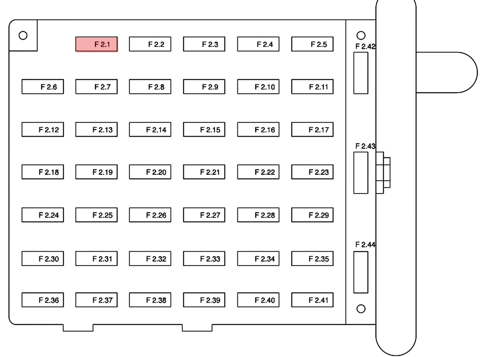
Purpose of the Under-Dash Fuse Box Diagram
The primary purpose of this diagram is to provide a visual representation of the fuses, relays, and their respective circuits located within the under-dash fuse box. Think of it as a roadmap for your car's electrical system. With it, you can quickly identify which fuse controls a specific component, making troubleshooting and repairs far easier. Forget blindly pulling fuses – this is about precision and efficiency.
Specifically, the diagram will help you:
- Diagnose electrical problems: Identify blown fuses associated with malfunctioning components.
- Perform repairs: Replace faulty fuses with the correct amperage rating.
- Install aftermarket accessories: Tap into appropriate circuits for powering new devices (e.g., adding a sub-woofer, aftermarket lights). Always do this carefully and with proper grounding and fuse protection.
- Learn your car's electrical system: Gain a deeper understanding of how various components are powered and protected.
Key Specs and Main Parts
The under-dash fuse box in the 2002 Mustang is typically located on the driver's side, beneath the steering wheel. You might need to contort yourself a bit to get a good look at it. It houses a collection of fuses and relays, each playing a critical role in protecting and controlling different electrical circuits.
Key Components:
- Fuses: These are sacrificial devices designed to protect circuits from overcurrent. They contain a thin wire that melts and breaks the circuit when the current exceeds a certain level. Fuses are rated in amperes (amps), which indicates the maximum current they can handle before blowing.
- Relays: Relays are electromechanical switches that use a small current to control a larger current. They're often used to switch high-current devices like headlights, fuel pumps, and starter motors. Relays help protect lower amperage circuits from being overloaded.
- Fuse Box Housing: This provides physical protection for the fuses and relays and also typically contains a label or diagram indicating the function of each fuse/relay.
- Connectors: These are the points where wires connect to the fuse box, providing power and ground to the various circuits.
Typical Fuse Ratings:
You'll find a range of fuse ratings in the fuse box, typically from 5 amps to 30 amps. Common ratings include 5A, 7.5A, 10A, 15A, 20A, 25A, and 30A. Never replace a fuse with a higher amperage rating than specified, as this can damage the circuit and potentially cause a fire.
Symbols and Diagram Interpretation
The fuse box diagram uses a combination of lines, colors, and icons to represent different components and their functions. Here's a breakdown of what you might encounter:
- Lines: Lines represent wires and circuits. Solid lines typically indicate positive (+) wires, while dashed lines might indicate ground (-) wires or wires with specific functions.
- Colors: Wire colors are often indicated on the diagram. For example, "RD" might indicate a red wire, "BL" a blue wire, "BK" a black wire (typically ground), and "WH" a white wire. Pay attention to these color codes, as they can help you trace wires within the vehicle.
- Icons/Labels: Icons and labels are used to identify the function of each fuse or relay. Common examples include:
- Headlight symbol: Indicates the fuse for the headlights.
- Radio symbol: Indicates the fuse for the radio.
- Wiper symbol: Indicates the fuse for the windshield wipers.
- PWR WDW: Power Windows.
- IGN: Ignition circuit.
The diagram will show each fuse and relay labeled with its corresponding circuit. For example, a fuse labeled "Cigar Lighter" protects the circuit for the cigarette lighter. A relay labeled "Fuel Pump" controls the power supply to the fuel pump.
How It Works: Basic Circuit Protection
Let's briefly review how the fuse system works in a typical automotive circuit.
- Power Source: The battery provides the initial source of electrical power.
- Circuit: The circuit consists of wires, switches, and the electrical component itself (e.g., a light bulb).
- Fuse: The fuse is placed in series within the circuit. This means that all current flowing to the component must pass through the fuse.
- Overcurrent: If there's a short circuit or an excessive current draw in the circuit, the current flowing through the fuse will increase dramatically.
- Fuse Blows: When the current exceeds the fuse's amperage rating, the thin wire inside the fuse melts, breaking the circuit and stopping the flow of current. This prevents damage to the component and other parts of the electrical system.
Real-World Use: Basic Troubleshooting
Here's a basic troubleshooting scenario using the fuse box diagram:
- Problem: Your radio suddenly stops working.
- Check the Fuse: Consult the fuse box diagram to identify the fuse associated with the radio (usually labeled as "Radio" or "Audio").
- Inspect the Fuse: Remove the fuse and visually inspect it. If the wire inside the fuse is broken or blackened, the fuse is blown.
- Replace the Fuse: Replace the blown fuse with a new fuse of the same amperage rating.
- Test: Turn on the radio to see if it works. If the radio still doesn't work, or if the new fuse blows immediately, there's likely a more serious problem in the radio circuit that requires further investigation. This could be a short circuit in the wiring or a faulty radio unit.
Important: If a fuse blows repeatedly, don't just keep replacing it. This indicates a underlying problem, such as a short circuit, that needs to be addressed. Ignoring the problem could lead to more serious damage or even a fire.
Safety: Highlight Risky Components
Working with electrical systems can be dangerous if you're not careful. Here are some safety precautions to keep in mind:
- Disconnect the Battery: Before working on any electrical components, disconnect the negative (-) terminal of the battery. This will prevent accidental shorts and electrical shocks.
- Use Insulated Tools: Use tools with insulated handles to avoid electrical shock.
- Avoid Water: Never work on electrical components in wet conditions.
- Handle Fuses Carefully: Fuses can be fragile, so handle them with care. Use a fuse puller tool to remove and install fuses to avoid damaging the fuse box or your fingers.
- High-Current Circuits: Be particularly cautious when working with circuits that carry high currents, such as those for the starter motor, alternator, and headlights. These circuits can deliver a powerful shock.
- Airbag Systems: Do not attempt to repair or modify the airbag system yourself. This is a very sensitive and potentially dangerous system that should only be handled by qualified technicians. Accidentally triggering an airbag can cause serious injury. The airbag system will typically have its own fuses and relays in the fuse box, but it's best to leave this system untouched unless you have the proper training and equipment.
Understanding your 2002 Ford Mustang's under-dash fuse box is a vital skill for any DIYer. By using the diagram, respecting safety precautions, and performing basic troubleshooting, you can tackle many electrical issues yourself and keep your Mustang running smoothly.
As mentioned, we have the complete 2002 Ford Mustang fuse box diagram available for you. You can download it by clicking [Download Link - Replace with Actual Link]. Keep it handy – you'll thank yourself later!