2002 Gmc Sierra Radio Wiring Diagram
For the experienced DIYer tackling audio upgrades, diagnosing electrical issues, or simply trying to understand the inner workings of your 2002 GMC Sierra's sound system, a wiring diagram is an indispensable tool. It's a roadmap to your radio's circuitry, helping you avoid costly mistakes and potential electrical damage. This guide breaks down the 2002 GMC Sierra radio wiring diagram, providing you with the knowledge to confidently navigate its intricacies.
Purpose of the Wiring Diagram
The primary purpose of a radio wiring diagram is to illustrate the electrical connections within the radio system. This includes the radio head unit, speakers, antenna, power sources, and ground connections. The diagram serves several crucial functions:
- Troubleshooting: Identifying the source of audio problems, such as a blown speaker, a malfunctioning antenna, or a short circuit.
- Installation: Facilitating the installation of aftermarket radios, amplifiers, or other audio components, ensuring proper connections and preventing damage to the vehicle's electrical system.
- Repair: Guiding the repair of damaged wiring or connectors.
- Understanding: Providing a comprehensive understanding of the radio system's electrical design.
Having a reliable wiring diagram eliminates guesswork, minimizes risks, and saves time and money by enabling accurate diagnostics and repairs.
Key Specs and Main Parts of the 2002 GMC Sierra Radio System
Before diving into the wiring diagram, let's establish the key components and their roles within the 2002 GMC Sierra's audio setup. Keep in mind that specifics may vary slightly depending on the trim level (e.g., SL, SLE, SLT) and optional equipment packages.
- Head Unit (Radio): The central control unit for the entire audio system, responsible for receiving radio signals, playing CDs, and controlling audio output. It includes power, ground, and speaker connections.
- Speakers: Convert electrical signals into audible sound. Typically, the 2002 Sierra has front (door) and rear (extended cab or crew cab) speakers.
- Antenna: Receives radio signals and sends them to the head unit.
- Power Supply: The radio requires a constant 12V (battery) power source for memory retention (station presets, etc.) and a switched 12V (ignition) power source to turn the radio on and off with the ignition key.
- Ground: Provides a return path for the electrical current, ensuring proper circuit operation. A solid, reliable ground connection is essential.
- Wiring Harness: A collection of wires bundled together and connected to the radio through a connector. This harness carries all the necessary signals and power to and from the radio.
- Chime Module: Some models might have a separate chime module integrated into the radio system, responsible for door chimes and warning sounds.
Understanding Wiring Diagram Symbols
A wiring diagram uses a standardized set of symbols to represent electrical components and connections. Deciphering these symbols is essential for understanding the diagram.
- Lines: Represent wires. Different colors indicate different functions (e.g., red for power, black for ground). The thickness of the line doesn't typically represent the wire gauge.
- Circles: Often represent components or connection points.
- Squares and Rectangles: Can represent various components, such as switches, relays, or modules.
- Ground Symbol: Usually looks like a series of decreasing horizontal lines connected to a vertical line, indicating a connection to the vehicle's chassis ground.
- Fuse Symbol: A jagged line within a circle or rectangle, indicating a fuse that protects the circuit from overcurrent.
- Connector Symbol: Depicts a connector where wires are joined together. The diagram will usually include a connector pinout, detailing which wire goes to which pin.
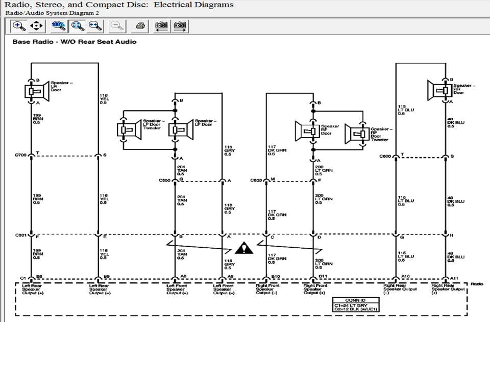
- Color Codes: The diagram will use standardized color codes for the wires (e.g., RED, BLK, WHT, GRN, BLU, YEL). Knowing these color codes is vital for identifying the correct wires.
- Abbreviations: Expect to see abbreviations like BATT (battery), IGN (ignition), GND (ground), SPKR (speaker), and ANT (antenna).
The key to using a wiring diagram effectively is understanding what each of these symbols represents. Before you start working on your Sierra's radio, spend some time familiarizing yourself with the symbols used in the diagram.
How the Radio Wiring Works
The 2002 GMC Sierra radio system operates on a relatively straightforward principle. The head unit receives power from the battery (for memory) and the ignition switch (for operation). When the ignition is turned on, the radio powers up. The head unit then processes radio signals received from the antenna or audio from a CD player. This audio signal is amplified and sent to the speakers, producing sound. A critical aspect is the grounding. A good ground connection ensures proper circuit operation and prevents unwanted noise or interference. The quality of the ground connection can greatly affect the audio performance.
Modern systems often include features such as a class 2 data bus for communication with the vehicle's computer system, especially for theft deterrent features. The wiring diagram will highlight any such integrated systems. Incorrect wiring can interfere with other vehicle functions.
Real-World Use and Basic Troubleshooting Tips
Here are a few common scenarios where a wiring diagram comes in handy, along with some basic troubleshooting tips:
- No Power to Radio: Check the fuses related to the radio circuit. The wiring diagram will show the location of the fuse panel and the fuse number. If the fuse is blown, replace it with one of the same amperage. Also, check the constant and switched 12V power wires with a multimeter to verify that they are receiving power.
- No Sound from Speakers: Check the speaker wiring connections. Make sure the speaker wires are properly connected to the head unit and the speakers. Use a multimeter to test the continuity of the speaker wires.
- Distorted Sound: This could indicate a blown speaker or a wiring issue. Inspect the speaker cone for damage. Also, check the speaker wiring for shorts or loose connections.
- Aftermarket Radio Installation: Use the wiring diagram to identify the correct wires for power, ground, speakers, and antenna. Match the wires from the aftermarket radio to the corresponding wires in the Sierra's wiring harness using a wiring adapter harness to avoid cutting factory wires.
When troubleshooting, always start with the simplest things first, such as checking the fuses and connections. A multimeter is your best friend when diagnosing electrical problems.
Safety Precautions
Working with automotive electrical systems can be dangerous if proper precautions are not taken. Here are some important safety tips:
- Disconnect the Battery: Before working on any electrical system, disconnect the negative terminal of the battery to prevent accidental short circuits.
- Use Proper Tools: Use insulated tools to avoid electrical shock.
- Work in a Well-Ventilated Area: Batteries can produce hydrogen gas, which is flammable.
- Never Work on Live Circuits: Unless absolutely necessary for testing, always disconnect the power source before working on any electrical component.
- Be Careful Around Airbags: Airbag systems are sensitive to electrical interference. Avoid working near airbag components unless you are properly trained.
- Fuses: Always replace a blown fuse with one of the same amperage. Using a higher amperage fuse can damage the wiring and create a fire hazard.
The risk of electrical shock and damage to the vehicle is real. If you are not comfortable working with electrical systems, consult a qualified technician.
Downloading the Diagram
Now that we've covered the fundamentals, it's time to get your hands on the actual wiring diagram. For your convenience, we have the complete 2002 GMC Sierra radio wiring diagram file available for you to download. This will allow you to have a clear, printable reference while working on your vehicle. With the diagram and this guide, you'll be well-equipped to tackle your audio projects.