
2002 Nissan Maxima Ignition Coil Diagram
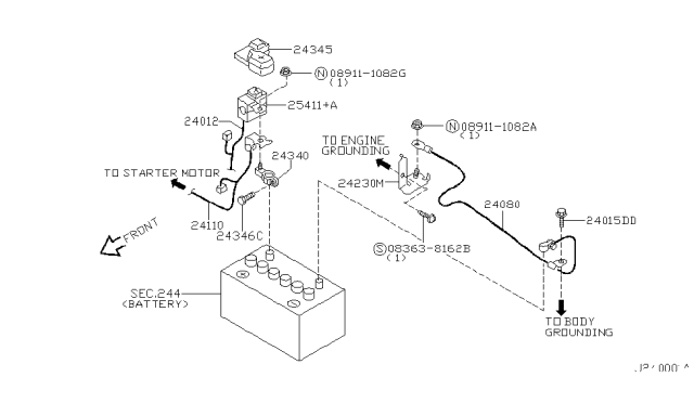
Alright, let's dive into the ignition coil diagram for a 2002 Nissan Maxima. This guide is designed for those of you who like to get your hands dirty and understand how your car ticks. We'll break down the diagram, explain the components, and give you some practical advice for troubleshooting. Having this knowledge and access to the diagram (which you can download - link at the end) will be invaluable if you're tackling ignition problems on your Maxima.
Purpose of the Ignition Coil Diagram
So, why bother with this diagram? Well, it's your roadmap to the ignition system. It's crucial for:
- Troubleshooting: Pinpointing the exact cause of a misfire, rough idle, or engine starting issues.
- Repairing: Accurately diagnosing and replacing faulty ignition coils, wiring, or related components.
- Understanding: Gaining a deeper knowledge of how your car's engine management system works.
- Modification (to a limited extent): Understanding the existing ignition system is crucial if you plan to make adjustments or upgrades to performance. You want to know your starting point!
Without the diagram, you're essentially guessing, which can lead to wasted time, money, and potential damage to your vehicle.
Key Specs and Main Parts of the 2002 Nissan Maxima Ignition System
The 2002 Nissan Maxima, specifically models equipped with the 3.5L V6 (VQ35DE) engine, use a distributorless ignition system, often referred to as a coil-on-plug (COP) system. This means each cylinder has its own dedicated ignition coil mounted directly above the spark plug. This is more efficient and reliable than older distributor-based systems.
Here's a breakdown of the key components:
- Ignition Coils: These are responsible for taking the relatively low voltage from the battery (around 12V) and stepping it up to a very high voltage (typically 20,000 - 30,000 volts) necessary to create a spark across the spark plug gap and ignite the air/fuel mixture in the cylinder.
- Spark Plugs: Located at the end of each cylinder, the spark plugs create the spark that ignites the air/fuel mixture.
- Engine Control Module (ECM): This is the brain of the operation. The ECM monitors various engine sensors and determines the precise timing and duration of the ignition signal sent to each coil.
- Crankshaft Position Sensor (CKP): This sensor provides the ECM with information about the crankshaft's position and speed, which is essential for accurate ignition timing.
- Camshaft Position Sensor (CMP): This sensor tells the ECM the position of the camshaft, further aiding in precise ignition and fuel injection timing.
- Wiring Harness: Connects all the components together, carrying the electrical signals.
- Ignition Relay: Provides power to the ignition system.
Understanding the Symbols on the Diagram
Navigating an electrical diagram can seem daunting at first, but it's really just a matter of understanding the symbols. Here's a guide:
- Lines: Lines represent wires. A solid line usually indicates a direct connection. Dashed lines may indicate shielded wiring or less critical connections.
- Colors: Each wire is typically color-coded. The diagram will have a legend that tells you what each color represents (e.g., Red = +12V, Black = Ground, Blue = Signal wire). Knowing the color code is critical for tracing wires and identifying potential shorts or breaks.
- Coil Symbol: The ignition coil itself is usually represented by a looped or coiled symbol, sometimes with an arrow indicating the direction of current flow.
- Ground Symbol: A series of descending lines or a triangle pointing down represents a ground connection. Good grounding is essential for the ignition system to function correctly.
- Connector Symbols: Connectors are represented by various shapes (circles, squares) and often have numbers indicating the pin assignments.
- Sensor Symbols: The crankshaft and camshaft position sensors will have their own symbols. Look for a "CRK" or "CMP" label near them.
Pay close attention to the legends on the diagram. They are your key to deciphering the symbols and abbreviations used.
How the Ignition System Works on a 2002 Maxima
Here's a simplified explanation of how the COP ignition system works on your 2002 Maxima:
- Sensors Provide Input: The CKP and CMP sensors send signals to the ECM about the crankshaft and camshaft positions. Other sensors, like the Mass Airflow Sensor (MAF) and Throttle Position Sensor (TPS), also provide data about engine load and operating conditions.
- ECM Calculates Ignition Timing: Based on the sensor data, the ECM determines the optimal ignition timing for each cylinder. Ignition timing refers to when the spark plug should fire in relation to the position of the piston in the cylinder.
- ECM Sends Signal to Coil: The ECM sends a low-voltage trigger signal to the appropriate ignition coil.
- Coil Amplifies Voltage: The ignition coil takes the low-voltage signal and rapidly discharges its stored energy, generating a high-voltage pulse. This works on the principle of electromagnetic induction – a rapid change in current in the primary winding of the coil induces a much higher voltage in the secondary winding.
- Spark Plug Fires: The high-voltage pulse travels to the spark plug, creating a spark across the gap. This ignites the air/fuel mixture in the cylinder, starting the combustion process.
Real-World Use: Basic Troubleshooting
Here are some troubleshooting tips using the ignition coil diagram:
- Misfire on a Specific Cylinder: If you have a misfire on a specific cylinder (e.g., P0301 - Cylinder 1 Misfire), use the diagram to identify the corresponding ignition coil and spark plug. Check the wiring harness for damage or loose connections. You can also try swapping the coil with a known good coil from another cylinder to see if the misfire follows the coil. If it does, the coil is likely faulty.
- No Start Condition: If the engine cranks but doesn't start, check for power and ground at the ignition coils. Use a multimeter to verify that the coils are receiving the proper voltage. The diagram will show you the power and ground wire locations. Also, check the crankshaft position sensor; a faulty CKP sensor will prevent the ECM from firing the ignition coils.
- Rough Idle: A rough idle can be caused by a variety of issues, including faulty ignition coils or spark plugs. Use the diagram to inspect the wiring and connections to the coils. Check for vacuum leaks, which can also affect engine performance.
- Use a Multimeter: A multimeter is your best friend when troubleshooting electrical problems. Use it to check for voltage, continuity, and resistance in the ignition system. The diagram will show you the expected voltage levels at various points.
Safety Precautions
Working with the ignition system can be dangerous due to the high voltages involved. Take the following precautions:
- Disconnect the Battery: Always disconnect the negative battery terminal before working on the ignition system. This will prevent accidental shocks and damage to the ECM.
- Wait for the System to Discharge: Even after disconnecting the battery, the ignition coils can still hold a residual charge. Wait a few minutes before touching any of the components.
- Use Insulated Tools: Use tools with insulated handles to prevent electric shocks.
- Avoid Working in Wet Conditions: Water conducts electricity, so avoid working on the ignition system in wet conditions.
- Be especially careful when working near the spark plugs while the engine is running. The voltage is extremely high and can cause serious injury.
Remember, if you're not comfortable working on the ignition system yourself, it's best to take your car to a qualified mechanic. However, with the right knowledge and tools, you can diagnose and repair many ignition problems yourself.
Final Notes
Keep in mind this information is intended as a general guide. Always refer to the specific service manual for your 2002 Nissan Maxima for the most accurate and up-to-date information.
As promised, we have the 2002 Nissan Maxima ignition coil diagram available for download. This will be invaluable for your repair and troubleshooting efforts. [Insert Link to Download Diagram Here]