
2002 Toyota Camry Exhaust System Diagram
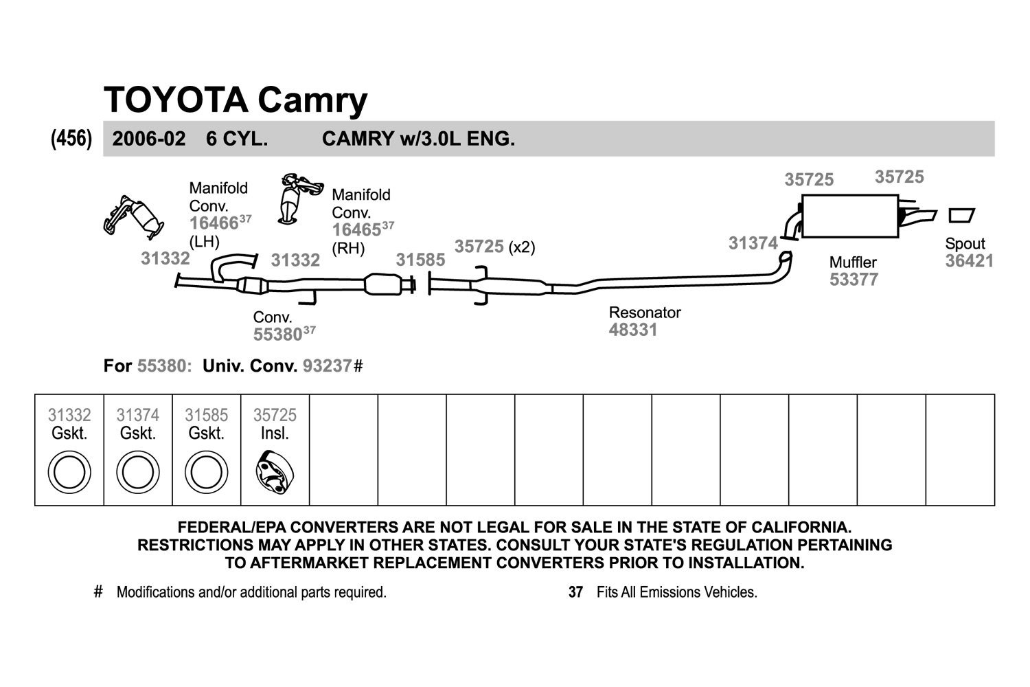
Alright, let's dive into the exhaust system of a 2002 Toyota Camry. This guide is designed for those of you comfortable turning a wrench and wanting a deeper understanding of how your Camry's exhaust works, why it's important, and how to troubleshoot common issues. We'll break down the diagram, explain its components, and give you some practical tips for working on it safely.
Purpose: Why Understand the 2002 Camry Exhaust Diagram?
Knowing your exhaust system is crucial for several reasons. First and foremost, it's essential for diagnosing and repairing problems. A rattling noise, poor fuel economy, or a failed emissions test can often be traced back to issues within the exhaust. Second, understanding the system allows for informed modifications. Want to upgrade to a performance muffler or headers? Knowing the stock setup ensures compatibility and proper installation. Finally, simply understanding how your car works is empowering! This diagram provides a visual roadmap of the entire system, making troubleshooting and maintenance much easier.
Key Specs and Main Parts
The 2002 Camry, depending on the engine (2.4L inline-4 or 3.0L V6), has slightly different exhaust configurations. We'll focus on the general principles applicable to both.
Main Components:
- Exhaust Manifold(s): These bolt directly to the engine's cylinder head(s) and collect exhaust gases from each cylinder. The V6 Camry has two manifolds, one for each bank of cylinders.
- Catalytic Converter(s): A critical component for emissions control. The catalytic converter uses a catalyst to convert harmful pollutants (like hydrocarbons, carbon monoxide, and nitrogen oxides) into less harmful substances. Camrys typically have one or two catalytic converters depending on the engine and emissions regulations.
- Resonator: This helps to reduce certain frequencies of sound, contributing to a quieter ride. Not all Camrys have a resonator.
- Muffler: The final sound-dampening device in the system. It uses baffles and sound-absorbing materials to significantly reduce exhaust noise.
- Exhaust Pipes: These connect all the components together, carrying the exhaust gases from the engine to the tailpipe.
- Oxygen Sensors (O2 Sensors): These sensors measure the amount of oxygen in the exhaust stream. The Engine Control Unit (ECU) uses this information to adjust the air-fuel mixture for optimal combustion and emissions. There are typically two sets: upstream (before the catalytic converter) and downstream (after the catalytic converter).
- Exhaust Hangers/Mounts: Rubber or metal hangers that support the exhaust system and isolate it from the car's chassis to prevent vibrations and noise from transferring into the cabin.
- Flanges and Gaskets: These create sealed connections between the different exhaust components.
Important Spec: The exhaust pipe diameter is a key spec. A common aftermarket modification is to increase exhaust pipe diameter to increase exhaust flow, resulting in higher horsepower. Too large a diameter can actually decrease horsepower, especially at lower RPMs.
Symbols on the Exhaust System Diagram
A good exhaust system diagram will use a standardized set of symbols. Here's a breakdown of common ones:
- Solid Lines: Represent the actual exhaust pipes. Thicker lines may indicate a larger diameter pipe.
- Dashed Lines: Often indicate heat shields or secondary components related to the exhaust system (e.g., vacuum lines for EGR – Exhaust Gas Recirculation – systems, if applicable).
- Arrows: Show the direction of exhaust gas flow.
- Rectangles: Usually represent catalytic converters, resonators, or mufflers. Some diagrams might use different shapes for each.
- Circles or Ovals: Typically indicate oxygen sensors. Some diagrams might differentiate between upstream and downstream sensors.
- Bolts and Flanges: Depicted as small circles or lines indicating connection points.
- Colors: While not always used, colors can sometimes indicate different materials or temperature zones within the exhaust system. For example, a reddish color might indicate areas that get very hot.
The legend or key on the diagram will define the specific meaning of each symbol used.
How the Exhaust System Works
The exhaust system's primary function is to safely and efficiently remove combustion gases from the engine. Here's the sequence:
- Exhaust Stroke: The engine's pistons push the burnt air-fuel mixture (exhaust gases) out of the cylinders.
- Exhaust Manifold Collection: The exhaust manifold(s) collect these gases from all cylinders and direct them into a single pipe (or two pipes in the case of a V6 with dual exhaust).
- Catalytic Conversion: The gases pass through the catalytic converter(s), where harmful pollutants are converted into less harmful substances using chemical reactions.
- Sound Dampening: The exhaust gases then travel through the resonator (if equipped) and the muffler, where sound waves are dampened and reduced.
- Discharge: Finally, the exhaust gases are expelled into the atmosphere through the tailpipe.
Oxygen sensors play a vital role in this process. They constantly monitor the oxygen levels in the exhaust stream. This data is sent to the ECU, which uses it to adjust the air-fuel mixture being injected into the engine. This feedback loop ensures optimal engine performance, fuel efficiency, and emissions control.
Real-World Use: Basic Troubleshooting Tips
Here are a few common exhaust system problems and how the diagram can help you diagnose them:
- Loud Exhaust/Rattling Noise: Check the exhaust hangers and mounts for damage or corrosion. The diagram shows their location, making it easier to inspect them. Also, inspect for holes in the pipes, muffler, or resonator. Follow the path of the exhaust on the diagram to pinpoint the source of the noise.
- Check Engine Light (CEL) with O2 Sensor Codes: Use the diagram to locate the specific O2 sensor triggering the code. Check the wiring and connections for damage before replacing the sensor. Remember to clear the code after the repair.
- Poor Fuel Economy/Performance: A clogged catalytic converter can restrict exhaust flow, leading to reduced performance and fuel economy. Visual inspection (though not always conclusive) and backpressure testing can help diagnose this. The diagram clearly shows the location of the catalytic converter.
- Exhaust Leaks: Listen for hissing or puffing sounds, especially near flanges and gaskets. Inspect these areas visually for soot or discoloration. The diagram highlights all the connection points.
Example: Let's say you hear a rattling noise coming from the rear of the car. Using the diagram, you can quickly identify the muffler and tailpipe area as potential sources. You then inspect the hangers in that area and the muffler itself for damage.
Safety Considerations
Working on an exhaust system can be dangerous. Here are some crucial safety tips:
- Hot Exhaust: Never work on the exhaust system when the engine is hot. Allow it to cool down completely to avoid severe burns.
- Jack Stands: Always use jack stands to support the vehicle when working underneath it. Never rely solely on a jack.
- Eye Protection: Wear safety glasses to protect your eyes from rust, dirt, and debris.
- Gloves: Wear gloves to protect your hands from sharp edges and contaminants.
- Welding (if applicable): If welding is required, take all necessary safety precautions, including wearing a welding helmet, gloves, and appropriate clothing. Disconnect the negative battery cable to prevent electrical damage.
- Carbon Monoxide: Never run the engine in an enclosed space while working on the exhaust. Carbon monoxide is a deadly gas.
- Penetrating Oil: Use penetrating oil on rusted bolts and connections to make disassembly easier and prevent damage.
- Catalytic Converter Precautions: While handling catalytic converters, avoid breathing any dust or fumes, and wash your hands thoroughly afterward. The materials inside the converter can be hazardous.
Risky Components: The catalytic converter gets extremely hot during operation and can remain hot for a considerable time after the engine is turned off. Be extremely careful when working near it. Also, be mindful of the sharp edges on exhaust pipes and flanges.
By understanding the 2002 Toyota Camry exhaust system diagram, you're well-equipped to diagnose problems, perform maintenance, and even make informed modifications. Always prioritize safety, and don't hesitate to consult a qualified mechanic if you're unsure about any aspect of the repair. Remember to follow proper safety procedures and take your time.
We have the complete 2002 Toyota Camry Exhaust System Diagram file available for download. This detailed resource will give you an even deeper understanding of your car's exhaust system. Contact us to request the file.