2003 Chevrolet Silverado Radio Wiring Harness
For the experienced DIYer tackling audio upgrades, repairs, or even custom electrical projects in a 2003 Chevrolet Silverado, understanding the radio wiring harness is crucial. This article will provide a comprehensive look at the 2003 Silverado radio wiring harness, covering its purpose, components, functionality, troubleshooting tips, and safety considerations. We'll break down the complexities into digestible information, enabling you to work with confidence. We even have the wiring diagram available for download at the end of the article.
Why Understanding the Radio Wiring Harness Matters
The radio wiring harness serves as the central communication hub between the radio and the vehicle's electrical system. Knowing its intricacies is essential for several reasons:
- Radio Replacement: Installing an aftermarket head unit requires interfacing with the existing harness. Understanding the pinouts and functions prevents damage and ensures proper integration.
- Speaker Upgrades: Upgrading speakers often involves tapping into the existing speaker wires within the harness. Identifying the correct wires is vital.
- Amplifier Installation: Installing an amplifier requires identifying the remote turn-on wire, power wire, and potentially tapping into the speaker outputs of the head unit.
- Troubleshooting Audio Problems: Diagnosing issues like a blown fuse, no sound, or distorted audio often involves inspecting the wiring harness for shorts, open circuits, or loose connections.
- Security System Integration: Some security systems tap into the radio wiring for features like theft detection or remote start.
Key Specs and Main Parts
The 2003 Silverado radio wiring harness consists of several key components and adheres to certain industry standards.
- Connectors: The harness typically uses one or two main connectors that plug directly into the back of the factory radio. These connectors are usually keyed to prevent incorrect insertion. The number of pins varies but often features a 12-pin and a 6-pin connector.
- Wire Gauge: The wires within the harness are typically between 16 and 18 gauge. Power wires (battery and ignition) may be thicker (14-16 gauge) to handle higher current.
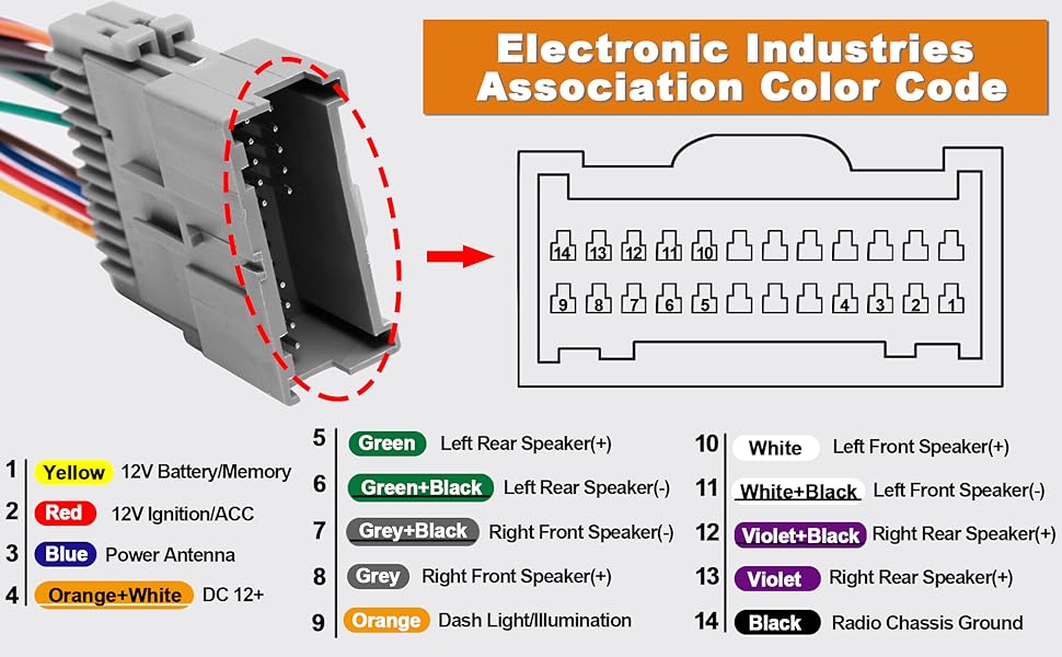
- Wire Color Coding: GM (General Motors) uses a standardized color-coding system for its wiring. Understanding these color codes is crucial for identifying the function of each wire. This is a vital piece of information we provide on our downloadable diagram.
- Main Wiring Functions: The harness contains wires for the following functions:
- Battery (B+): Provides constant power to the radio for memory retention.
- Ignition (ACC): Provides power to the radio when the ignition is turned on.
- Ground: Provides a return path for the electrical current.
- Illumination: Dim the radio display when the headlights are turned on.
- Power Antenna: Activates the power antenna (if equipped) when the radio is turned on.
- Remote Turn-On: Activates external amplifiers.
- Speakers (Left Front, Right Front, Left Rear, Right Rear): Carries the audio signal to the speakers.
- Chime Module: Provides the audible warning chimes (e.g., door open, key in ignition). This can be affected when swapping out the factory head unit, sometimes requiring a separate adapter module.
- Data Lines (Serial Data): Provides communication with other vehicle modules, such as the Body Control Module (BCM).
Decoding the Wiring Diagram: Symbols and Conventions
A wiring diagram is a schematic representation of the electrical circuit. Understanding the symbols and conventions used in the diagram is essential for interpreting it correctly.
- Lines: Solid lines represent wires. Dashed lines often represent shielded cables or communication lines.
- Colors: Each wire is identified by a specific color code. This color code is usually abbreviated (e.g., RED, BLU, GRN). The diagram includes a key that translates these abbreviations.
- Connectors: Connectors are typically represented by geometric shapes, such as circles or rectangles. The diagram indicates the pin numbers within each connector.
- Components: Components like the radio, speakers, and fuses are represented by standardized symbols.
- Ground: Ground connections are typically represented by a symbol resembling an inverted pyramid or a series of horizontal lines.
- Splices: Splices (where two or more wires are joined) are indicated by dots or small circles at the junction of the wires.
Important Note: Always consult the specific wiring diagram for your 2003 Silverado, as there may be slight variations depending on the trim level and optional equipment.
How It Works: Signal Flow
The radio's operation depends on the proper flow of electrical signals through the wiring harness. Here's a simplified explanation:
- Power Supply: The battery (B+) provides constant power to the radio for memory and clock functions. The ignition (ACC) wire provides power when the ignition is turned on, activating the radio.
- Ground Connection: The ground wire provides a return path for the electrical current, completing the circuit.
- Signal Input: The radio receives audio signals from various sources, such as the antenna, CD player, or auxiliary input.
- Signal Processing: The radio processes the audio signal, amplifies it, and sends it to the speakers.
- Speaker Output: The amplified audio signal is sent to the speakers via the speaker wires in the harness. Each speaker has a positive and a negative wire.
- Illumination Control: When the headlights are turned on, the illumination wire signals the radio to dim the display, reducing glare.
Real-World Use: Basic Troubleshooting
Understanding the radio wiring harness can help you troubleshoot common audio problems. Here are a few examples:
- No Power to Radio: Check the battery (B+) and ignition (ACC) wires for voltage using a multimeter. Also, check the radio fuse in the fuse box. A blown fuse is a common culprit.
- No Sound from Speakers: Check the speaker wires for continuity using a multimeter. Ensure the speaker wires are properly connected to the radio. A break in the wire is also a possibility.
- Distorted Sound: Check the speaker wires for shorts to ground. Replace damaged speakers.
- Radio Turns On and Off Intermittently: Check for loose connections in the wiring harness. Inspect the ignition wire for proper voltage.
- Chime Sounds Not Working: If you've replaced the factory radio, you may need a chime adapter module to retain the functionality of the chime sounds.
Tip: Before working on the wiring harness, disconnect the negative battery terminal to prevent electrical shock.
Safety Considerations
Working with electrical systems can be dangerous. Here are some safety precautions to keep in mind:
- Disconnect the Battery: Always disconnect the negative battery terminal before working on the electrical system.
- Use Proper Tools: Use insulated tools to prevent electrical shock.
- Avoid Water: Never work on the electrical system in wet conditions.
- Identify Hot Wires: Be cautious when working near hot wires (wires that carry voltage).
- Airbags: Be extremely careful around airbag modules and wiring. Accidental activation of an airbag can cause serious injury. If you are unsure about how to handle airbags, consult a qualified technician.
The airbag system wires are often bright yellow and have specific connectors. Do not tamper with them unless you are a qualified technician.
By following these safety precautions, you can minimize the risk of electrical shock and injury.
Download the 2003 Chevrolet Silverado Radio Wiring Diagram
We have compiled a detailed wiring diagram for the 2003 Chevrolet Silverado radio wiring harness. This diagram includes all the necessary information for identifying the functions of each wire, including wire colors, pin locations, and connector types. This document will be an invaluable resource when working on your project. Contact us through our website to obtain the file.