2003 Chevy Silverado 1500 Radio Wiring Diagram
The 2003 Chevy Silverado 1500 is a workhorse, and a properly functioning radio is crucial for many drivers. Understanding the radio wiring diagram is invaluable whether you're tackling a repair, upgrading your sound system, or simply learning more about your truck's electrical system. This guide will provide a detailed breakdown of the 2003 Silverado 1500 radio wiring diagram, enabling you to confidently diagnose and address any radio-related issues.
Purpose of the Wiring Diagram
The wiring diagram serves as a roadmap to your truck's radio electrical system. It illustrates how each component, from the head unit (radio itself) to the speakers and antenna, is interconnected. This knowledge is vital for several reasons:
- Troubleshooting: Identify breaks in circuits, shorts, or faulty components.
- Installation: Connect aftermarket radios, amplifiers, or speakers correctly.
- Repair: Replace damaged wiring or connectors.
- Modification: Customize your audio system, such as adding a subwoofer.
- Learning: Gain a deeper understanding of automotive electrical systems.
Key Specs and Main Parts
Before diving into the diagram itself, let's identify the key components of the 2003 Silverado 1500 radio system. Understanding their functions is critical for interpreting the wiring diagram effectively.
- Head Unit (Radio): The brain of the system. It receives power, processes audio signals, and provides outputs to speakers and other components. It typically includes the AM/FM tuner, CD player (if equipped), and controls for volume, tone, and station selection.
- Speakers: Convert electrical signals into audible sound. The 2003 Silverado typically has four speakers: two in the front doors and two in the rear doors (or behind the seats in extended cab models).
- Antenna: Receives radio signals from broadcasting stations.
- Wiring Harness: A bundle of wires that connects the head unit to the vehicle's electrical system and the speakers. It's often connected to the head unit via a specific connector.
- Ground Connection: A wire that connects the radio to the vehicle's chassis, providing a return path for electrical current. A good ground is essential for proper radio operation.
- Power Source: The battery provides the power. The radio typically has two power wires: one for constant power (to retain memory settings) and one for switched power (activated when the ignition is on).
- Fuse: A safety device that protects the radio circuit from overcurrent. It is crucial to locate and check the fuse first when troubleshooting radio problems.
- Chime Module: In some models, the radio system is integrated with the chime module, which produces warning sounds (e.g., door ajar, seatbelt reminder). Disconnecting the radio improperly can sometimes affect these chimes.
Decoding the Symbols
Wiring diagrams use standard symbols to represent electrical components and connections. Understanding these symbols is essential for deciphering the diagram. Here are some of the most common symbols you'll encounter:
- Solid Lines: Represent wires. The thickness of the line doesn't usually indicate wire gauge.
- Dashed Lines: Can represent shielding or connections that are not directly part of the main circuit being shown.
- Circles: Often represent connectors or terminals.
- Squares: Can represent components like resistors or capacitors.
- Ground Symbol (usually three horizontal lines diminishing in size): Indicates a connection to ground.
- Battery Symbol: Represents the vehicle's battery.
- Speaker Symbol: A circle with a line bisecting it.
Wire Colors: Wire colors are critical for identifying specific wires in the harness. The 2003 Silverado uses a variety of colors, and the wiring diagram will specify the color of each wire and its corresponding function. Common colors include:
- Red: Usually indicates constant power.
- Yellow: Often indicates switched power.
- Black: Almost always indicates ground.
- White: Often used for speaker wires, but can vary.
- Green, Blue, Brown, Gray, and other colors: Used for various functions, including speaker wires, data signals, and accessory control.
The specific color codes can be found within the wiring diagram itself.
How It Works: A Simplified Explanation
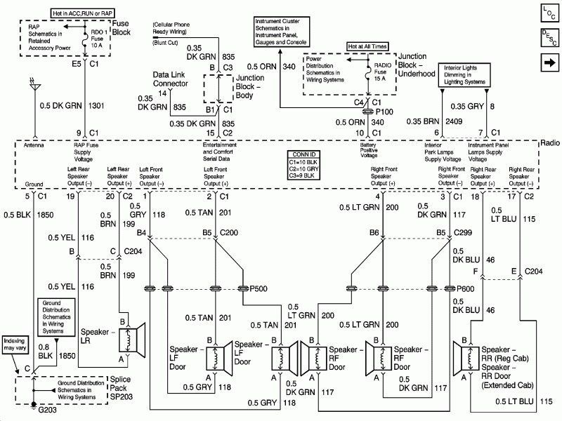
The radio system operates in a straightforward manner. The antenna receives radio signals, which are then fed to the head unit. The head unit amplifies and processes these signals, converting them into audible sound that is sent to the speakers. The head unit receives power from the vehicle's battery through two main lines: one for constant power and one for switched power. The constant power ensures that the radio retains its memory settings (e.g., preset stations), while the switched power allows the radio to turn on and off with the ignition.
The wiring diagram shows how these components are interconnected, including the specific wires that carry power, ground, and audio signals. It also shows the location of fuses and other protective devices. Knowing the flow of electricity through the circuit helps you pinpoint problems when they arise. For instance, if the radio has no power, you would first check the fuses associated with the radio circuit. If the fuses are good, you would then use the wiring diagram to trace the power and ground wires to identify any breaks or shorts in the circuit. Proper grounding is especially important. A bad ground connection will cause all sorts of erratic behavior.
Real-World Use: Basic Troubleshooting
Here are a few common radio-related problems and how the wiring diagram can help you diagnose them:
- Radio has no power: Check the fuses first. Use the wiring diagram to locate the correct fuse. If the fuse is blown, replace it. If it blows again immediately, there is a short circuit in the wiring. Use the diagram to trace the power and ground wires to identify the location of the short.
- Radio turns on, but no sound: Check the speaker connections. Use the wiring diagram to identify the speaker wires and ensure they are properly connected to the speakers. If the connections are good, the problem may be a faulty speaker or a problem within the head unit.
- Poor radio reception: Check the antenna connection. Use the wiring diagram to identify the antenna wire and ensure it is securely connected to the head unit. The antenna itself might be damaged.
- One speaker not working: Test the speaker directly with a multimeter to check its impedance. If the speaker is fine, trace the wires to the head unit to look for damage.
- Chimes don't work after radio replacement: Verify the aftermarket harness is properly wired for chime functionality. You may need an adapter to retain chime functionality. The wiring diagram will show how the original radio was connected to the chime module.
Safety Precautions
Working with automotive electrical systems can be dangerous. Always disconnect the negative terminal of the battery before working on any electrical components. This will prevent accidental shorts and electrical shocks.
Airbag Systems: The radio system may be near or integrated with airbag control modules. *Never* disconnect or tamper with airbag-related wiring unless you are specifically trained to do so. Incorrectly handling airbag systems can result in serious injury or death.
Always use proper wiring tools and techniques to ensure secure and reliable connections. Use heat shrink tubing to insulate splices and prevent corrosion.
Always double-check your work before reconnecting the battery.
We have the complete 2003 Chevy Silverado 1500 Radio Wiring Diagram available for download. Please click [link to download] to access the file. This resource will provide the specific details you need for your truck's configuration. Remember to use the diagram in conjunction with a multimeter and other basic tools to diagnose and resolve any radio-related issues.